Current detection device

a detection device and current technology, applied in the direction of measurement devices, current measurements only, instruments, etc., can solve the problems of deteriorating productivity, difficult pressing, and inability to large the thickness of the busbar (dimensional value in a vertical direction), so as to achieve the effect of not reducing productivity

Active Publication Date: 2020-05-21
YAZAKI CORP
View PDF0 Cites 4 Cited by
  • Summary
  • Abstract
  • Description
  • Claims
  • Application Information

AI Technical Summary

Benefits of technology

[0009]The foregoing configuration affords the effect of making it possible to provide a current detection device capable of detecting a large electric current without reducing productivity.

Problems solved by technology

However, when productivity is considered, the thickness of the busbar (dimensional value in a vertical direction) cannot be large.
For example, when the busbar thickness exceeds 3 mm, processing such as presswork is difficult, and productivity deteriorates.
However, when the busbar width is made large, there is a problem in that the lateral dimension of the current detection device (the shield member) ends up being large.

Method used


Image

  • Current detection device
  • Current detection device
  • Current detection device

Examples


Embodiment Construction

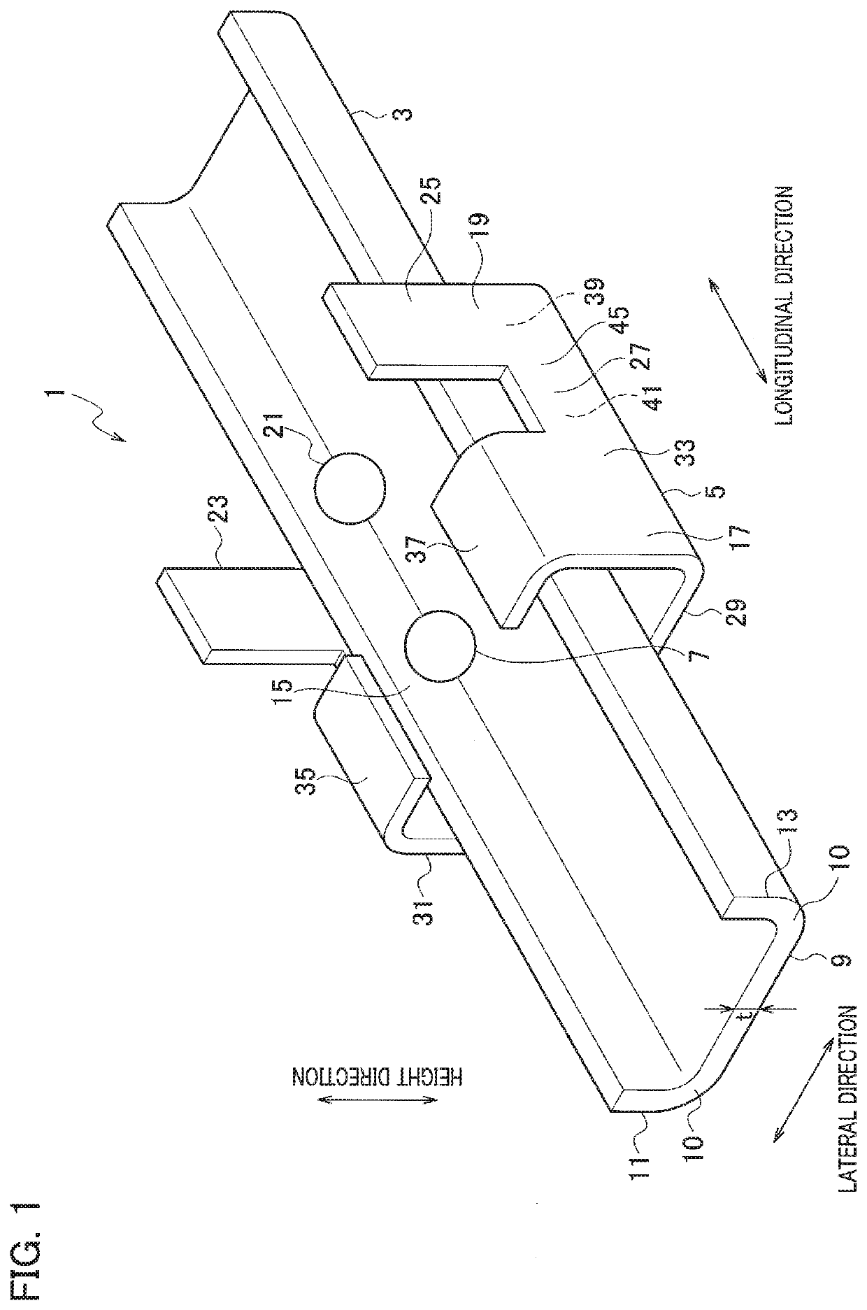
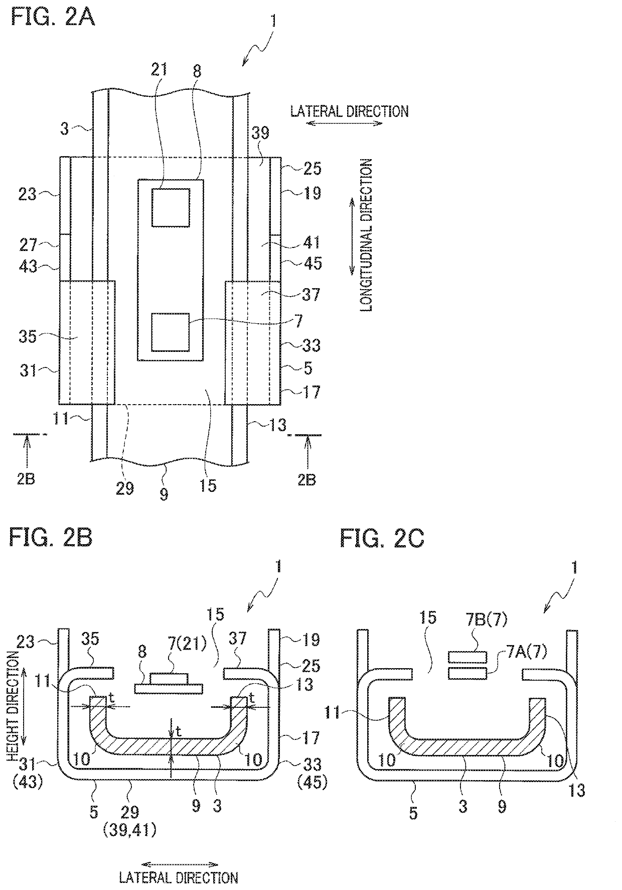
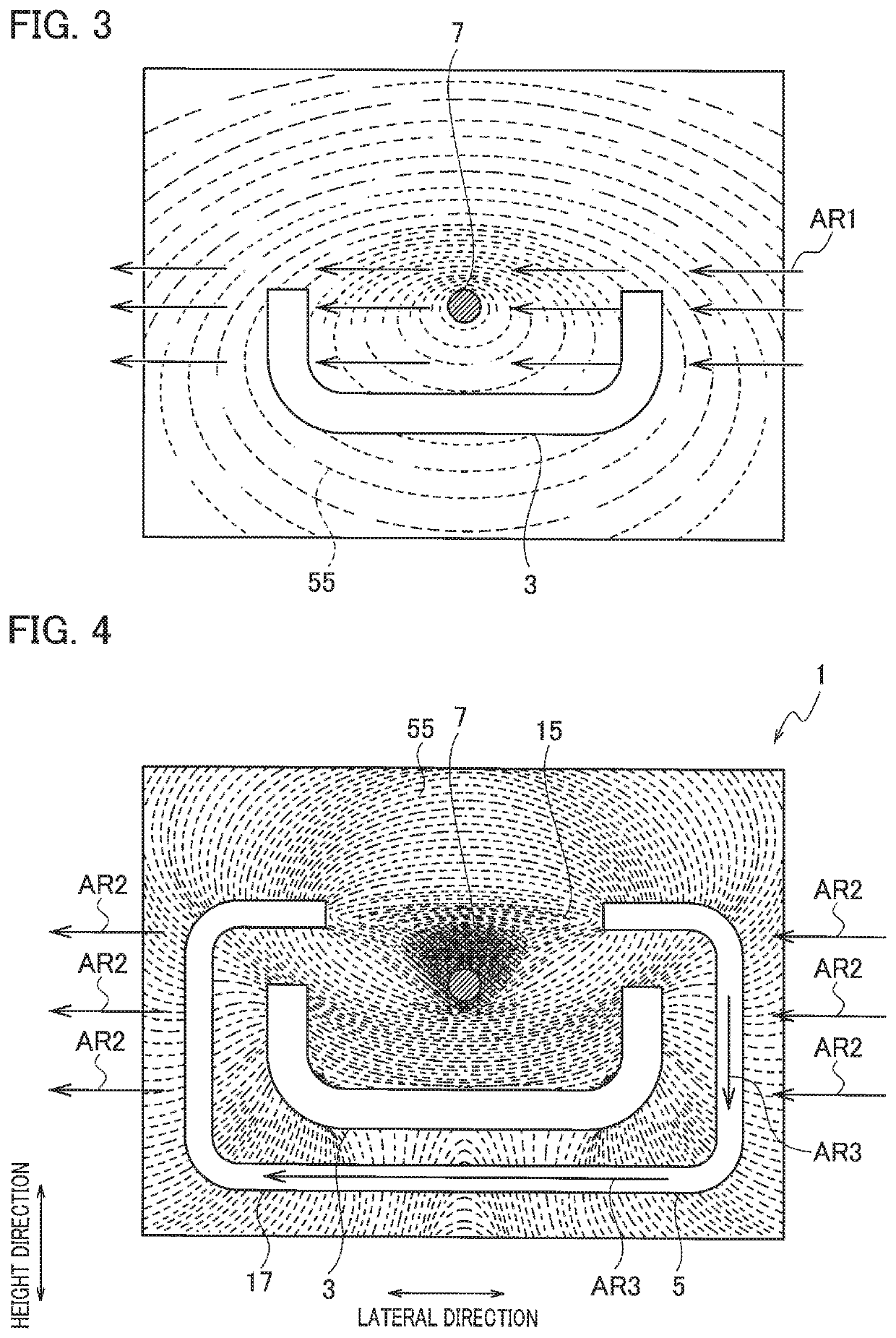
[0026]A current detection device 1 according to the embodiment of the present disclosure detects an electric current flowing in a busbar 3 by detecting a magnetic field 55 (see FIG. 4) generated by the electric current flowing in the busbar 3. The current detection device 1 includes the busbar 3, a shield member 5, and a current sensor (magnetic field detecting element; Hall IC) 7, as illustrated in FIGS. 1, 2A, and 2B.

[0027]To facilitate the explanation, a predetermined direction is a longitudinal direction, a predetermined direction that is orthogonal to the longitudinal direction is a lateral direction, and a direction that is orthogonal to the longitudinal direction and lateral direction is a height direction.

[0028]The shield member 5 is configured from a ferromagnetic body (permalloy, for example, which is an alloy of iron and nickel). The shield member 5 includes a second portion 19 in addition to a first portion 17. The first portion 17 and second portion 19 are arranged at b...


PUM


Abstract

In a current detection device, a busbar extends through the interior of a shield member. The busbar is thin in thickness and yet is bent, when viewed in a direction of extension. A current sensor detects a magnetic field generated by an electric current flowing in the busbar.

Description

BACKGROUNDTechnical Field[0001]The present disclosure relates to a current detection device, and more particularly to a current detection device that detects an electric current flowing in a busbar by detecting a magnetic field generated by the electric current flowing in the busbar.Related Art[0002]A conventional current detection device includes a busbar, a shield member, and a current sensor.[0003]The current detection device is configured to detect the value of an electric current flowing in a shield member as a result of a current sensor detecting a magnetic field that is generated when the electric current is flowing in the shield member (JP 2017-215143 A).SUMMARY[0004]When the value of the electric current flowing in the busbar of the current detection device is large, the cross-sectional area of the busbar must be made large.[0005]However, when productivity is considered, the thickness of the busbar (dimensional value in a vertical direction) cannot be large. For example, wh...

Claims


Application Information

Patent Timeline
Patent Type & Authority Applications(United States)
IPC IPC(8): G01R15/20G01R19/00
CPCG01R19/0092G01R15/202G01R15/207G01R1/18
Inventor FUKUHARA, TOSHIAKI
Owner YAZAKI CORP
Why Eureka
Try Eureka