Contactor assembly for distribution board

Active Publication Date: 2020-05-21
LSIS CO LTD
View PDF13 Cites 4 Cited by
  • Summary
  • Abstract
  • Description
  • Claims
  • Application Information

AI Technical Summary

Benefits of technology

[0011]The present disclosure is devised to solve the above-mentioned problems of the prior art. The present disclosure is to provide a cont

Problems solved by technology

However, the bifurcated tongs type contactor has a disadvantage in that durability deteriora

Method used


Image

  • Contactor assembly for distribution board
  • Contactor assembly for distribution board
  • Contactor assembly for distribution board

Examples


Example

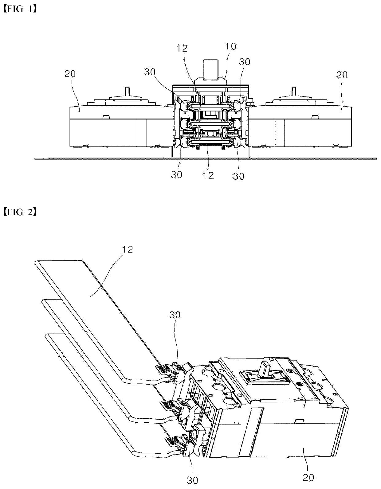
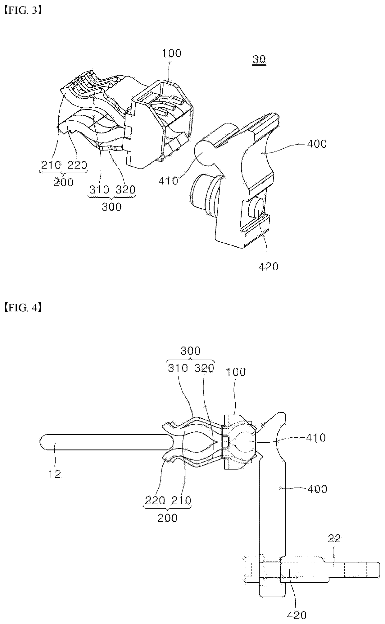
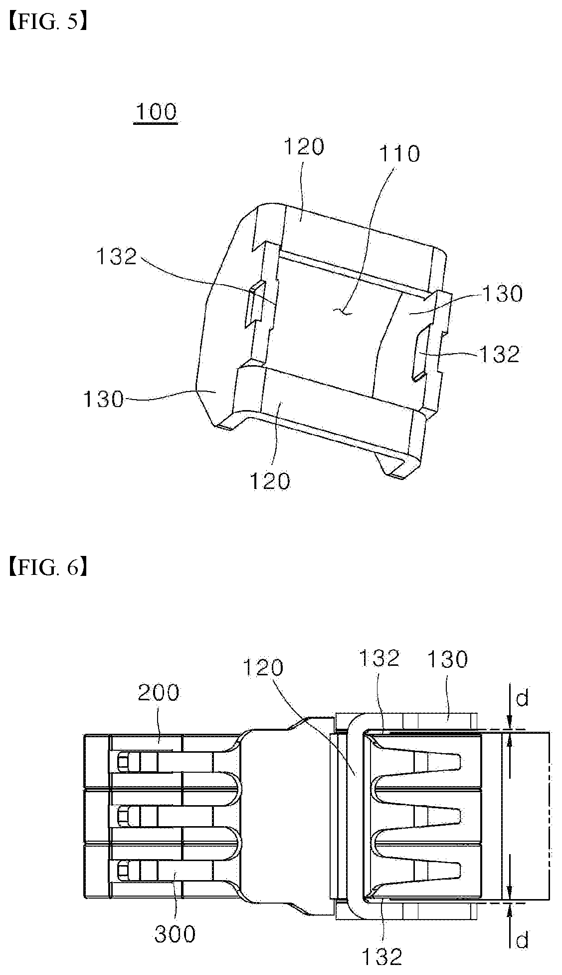
[0032]For simplicity and clarity of illustration, elements in the figures are not necessarily drawn to scale. The same reference numbers in different figures denote the same or similar elements, and as such perform similar functionality. Furthermore, in the following detailed description of the present disclosure, numerous specific details are set forth in order to provide a thorough understanding of the present disclosure. However, it will be understood that the present disclosure may be practiced without these specific details. In other instances, well-known methods, procedures, components, and circuits have not been described in detail so as not to unnecessarily obscure aspects of the present disclosure.

[0033]Examples of various embodiments are illustrated and described further below. It will be understood that the description herein is not intended to limit the claims to the specific embodiments described. On the contrary, it is intended to cover alternatives, modifications, and...


PUM


Abstract

A contactor assembly is connected to a bus-bar of a main circuit-breaker. The assembly includes a housing including an opening defined therein; a contactor passing through the opening, wherein the contractor includes contacting portions projecting forwardly of the opening and coupled portions projecting rearwardly of the opening; a presser passing through the opening, wherein the presser is interposed between the contactor and the housing, wherein the presser is supported on the housing and presses the contacting portions and the coupled portions; and a connector coupled to the coupled portions of the contactor and electrically connected to the contactor.

Description

CROSS-REFERENCE TO RELATED APPLICATIONS[0001]Pursuant to 35 U.S.C. § 119(a), this application claims the benefit of earlier filing date and right of priority to Korean Application No. 10-2018-0144531 filed on Nov. 21, 2018, in the Korean Intellectual Property Office, the disclosure of which is hereby incorporated by reference in its entirety.BACKGROUND1. Technical Field[0002]The present disclosure relates to a contactor assembly connecting a branching circuit-breaker and a main circuit-breaker with each other in a distribution board.2. Description of the Related Art[0003]In general, a distribution board receives power from a main line and distributes the power according to a purpose. The distribution board includes a main circuit-breaker connected to the main line. The main circuit-breaker is connected to multiple branching circuit-breakers to distribute power through each branching circuit-breaker.[0004]Therefore, the distribution board has a structure in which the plurality of bra...

Claims


Application Information

Patent Timeline
IPC IPC(8): H01H71/08H01H71/10H02B1/20
CPCH01H71/08H01H71/1009H02B1/20H01H73/04H01H73/20H01H2001/425H01H1/42H01H2011/0037H01R25/142H01R13/113H01R13/18H02B1/056H01R12/00H01R13/2407
Inventor SEO, JAE-KWAN
Owner LSIS CO LTD
Why Eureka
Try Eureka