
Electric-assisted power steering apparatus

a technology of electric assisted power steering and power steering shaft, which is applied in the direction of electric steering, power driven steering, vehicle components, etc., can solve the problems of inability to obtain the intended amount of assistance torque, and inability to steer the vehicle, so as to reduce the size and fabrication cost of the motor, promote the safety of the driver, and increase the rotation speed of the motor

Active Publication Date: 2020-05-28
HL MANDO CORP
View PDF0 Cites 3 Cited by
  • Summary
  • Abstract
  • Description
  • Claims
  • Application Information

AI Technical Summary

Benefits of technology

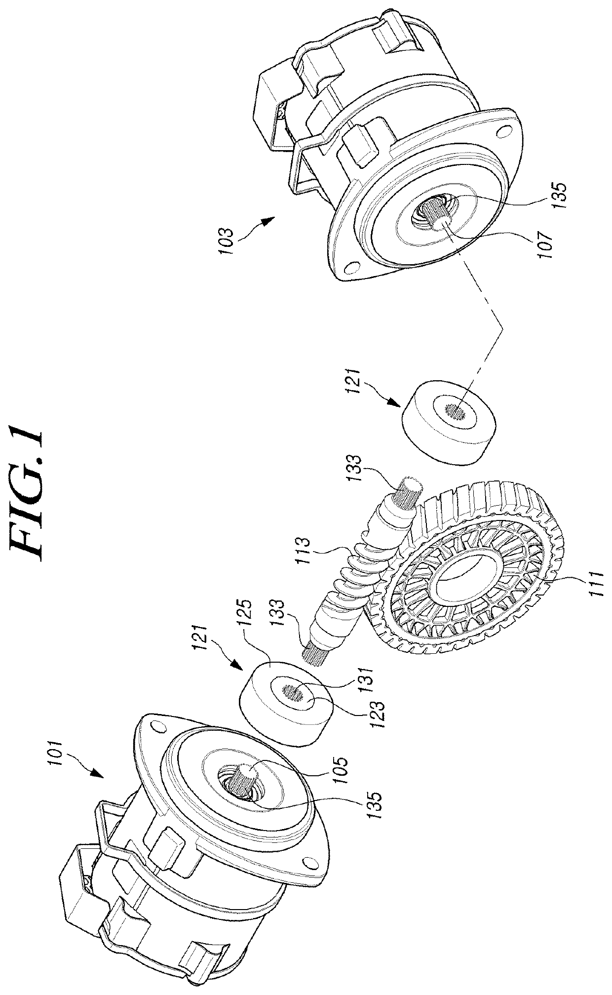
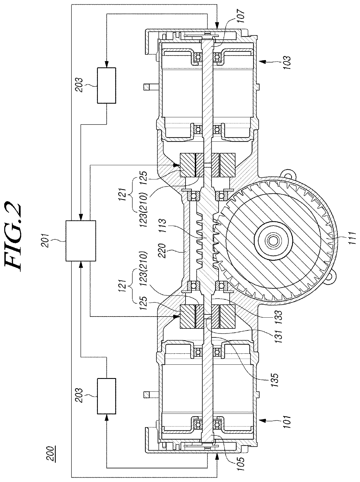
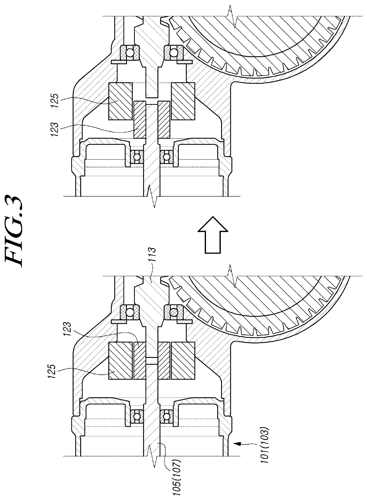
The electric assisted power steering apparatus described in this patent allows for the disconnection of a worm shaft from any malfunctioning motors connected to its ends, preventing the worm shaft from rotating excessively or failing to rotate. This also allows for an increase in the rotation speed of the properly-operating motor to prevent sudden changes in auxiliary torque on the steering shaft, improving driver safety. Additionally, torque required for the worm shaft can be distributed to two motors, increasing their rotation speeds and reducing their size and fabrication costs.

Problems solved by technology

However, in a case in which the motor does not operate properly due to a mechanical failure, such as contact between a rotor and a stator within a motor, or an electrical failure, such as overloading, a short circuit, or malfunctioning in a sensor, an intended amount of assistance torque cannot be obtained.
In particular, in a steer-by-wire (SbW) steering apparatus for steering a vehicle using electrical power without a mechanical connection between a steering wheel and a front wheel steering device, vehicle steering may be impossible when the motor malfunctions.
However, in the electric power steering apparatus of the related art, the motor shaft of the malfunctioning motor may not be disconnected from the worm shaft.
This may cause the rotation of the worm shaft to be heavier to reduce assistance torque or may prevent the rotation of the worm shaft so that assistance torque cannot be generated.

Method used


Image

  • Electric-assisted power steering apparatus
  • Electric-assisted power steering apparatus
  • Electric-assisted power steering apparatus

Examples


Embodiment Construction

[0018]In the following description of examples or embodiments of the present disclosure, reference will be made to the accompanying drawings in which it is shown by way of illustration specific examples or embodiments that can be implemented, and in which the same reference numerals and signs can be used to designate the same or like components even when they are shown in different accompanying drawings from one another. Further, in the following description of examples or embodiments of the present disclosure, detailed descriptions of well-known functions and components incorporated herein will be omitted when it is determined that the description may make the subject matter in some embodiments of the present disclosure rather unclear. The terms such as “including”, “having”, “containing”, “constituting”“make up of”, and “formed of” used herein are generally intended to allow other components to be added unless the terms are used with the term “only”. As used herein, singular forms...


PUM


Abstract

Provided is an electric assisted power steering apparatus having a structure able to disconnect a worm shaft from any malfunctioning motor of motors connected to opposite end portions of the worm shaft, thereby preventing the worm shaft from rotating heavily or failing to rotate. Even in the case in which the worm shaft is disconnected from the malfunctioning motor, a target rotation speed of the properly-operating motor is increased to prevent sudden changes in auxiliary torque occurring on a steering shaft, thereby promoting the safety of a driver. Torque required for the worm shaft is distributed to the two motors, thereby increasing the rotation speeds of the motors and reducing the size and fabrication costs of the motors.

Description

CROSS REFERENCE TO RELATED APPLICATION[0001]This application claims priority from Korean Patent Application No. 10-2018-0146557, filed on Nov. 23, 2018, which is hereby incorporated by reference for all purposes as if fully set forth herein.BACKGROUNDField[0002]Embodiments relate to an electric assisted power steering apparatus and, more particularly, to an electric assisted power steering apparatus having a structure able to disconnect a worm shaft from any malfunctioning motor of motors connected to opposite end portions of the worm shaft, thereby preventing the worm shaft from rotating heavily or failing to rotate. Even in the case in which the worm shaft is disconnected from the malfunctioning motor, a target rotation speed of the properly-operating motor can be increased to prevent sudden changes in auxiliary torque occurring on a steering shaft, thereby promoting the safety of a driver. Torque required for the worm shaft can be distributed to the two motors, thereby increasing...

Claims


Application Information

Patent Timeline
Patent Type & Authority Applications(United States)
IPC IPC(8): B62D5/04B62D3/04
CPCB62D5/0424B62D5/0487B62D5/0484B62D3/04B62D5/0409B62D5/0478B62D5/0436B62D5/04B62D5/0463B62D5/0454B62D5/0403B60Y2400/307B60Y2400/303
Inventor KIM, TAE SIK
Owner HL MANDO CORP
Learn More