Compressor impeller

a compressor and impeller technology, applied in the field of compressor impellers, can solve the problems of reducing the compressor efficiency, deteriorating the performance of the compressor impeller, and reducing the compressor pressure ratio, so as to prevent the configuration of the casing side from becoming complex, and suppressing the temperature increase of the back surface

Active Publication Date: 2020-05-28
MITSUBISHI HEAVY IND ENGINE & TURBOCHARGER LTD
View PDF5 Cites 1 Cited by
  • Summary
  • Abstract
  • Description
  • Claims
  • Application Information

AI Technical Summary

Benefits of technology

[0037]According to at least one embodiment of the present invention, it is possible to provide a compressor impeller whereby it is possible to suppress a temperature increase of a back surface of a boss portion of the compressor impeller, while preventing the configuration of the casing side from becoming complex.

Problems solved by technology

When the temperature of the air flowing along the compressor impeller 050 is increased from heat transmission from the boss portion 002 and the vane portion 004, it leads to deterioration of the performance of the compressor impeller 050, that is, reduction of the compressor pressure ratio and reduction of the compressor efficiency.

Method used


Image

  • Compressor impeller
  • Compressor impeller
  • Compressor impeller

Examples


Embodiment Construction

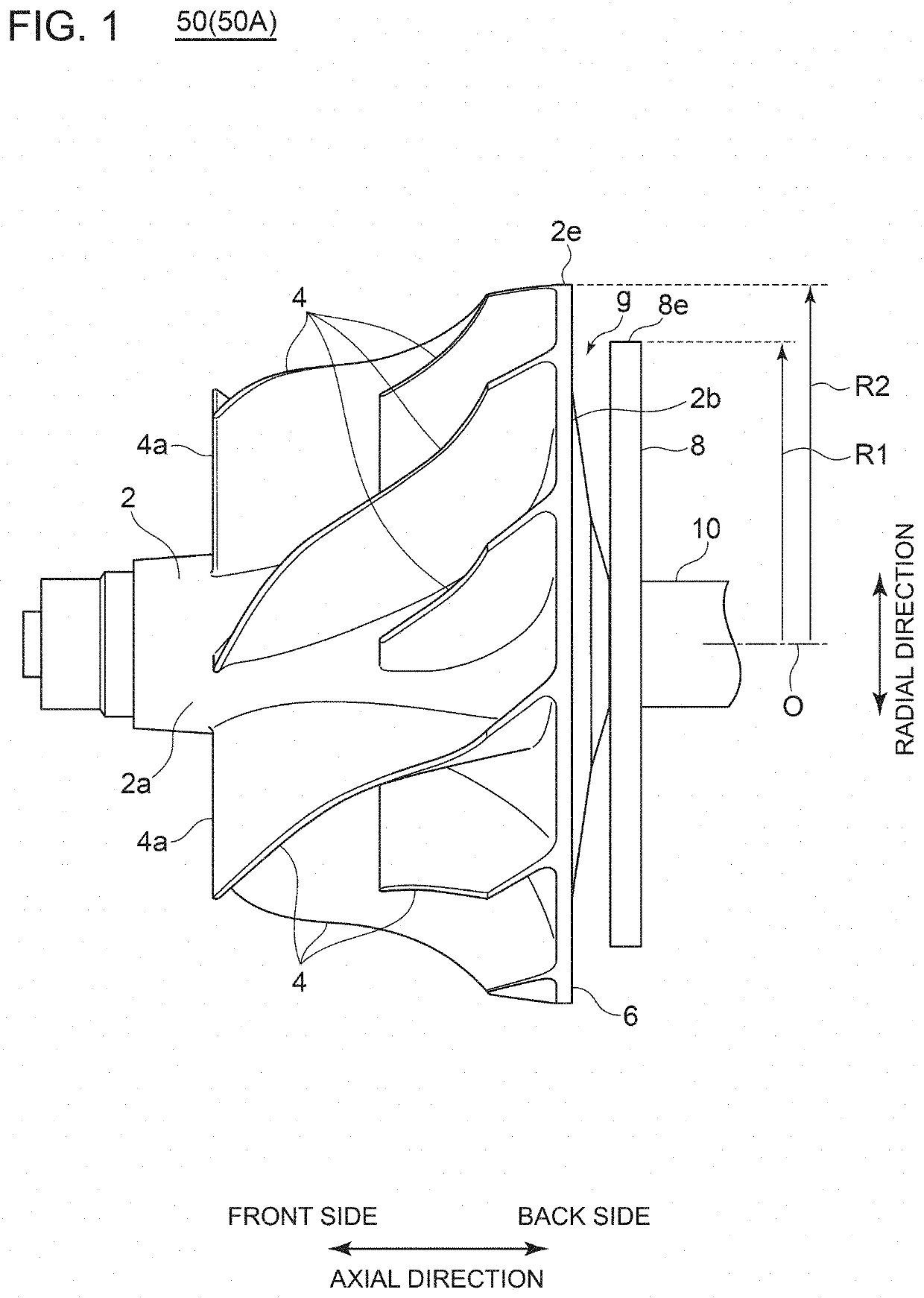
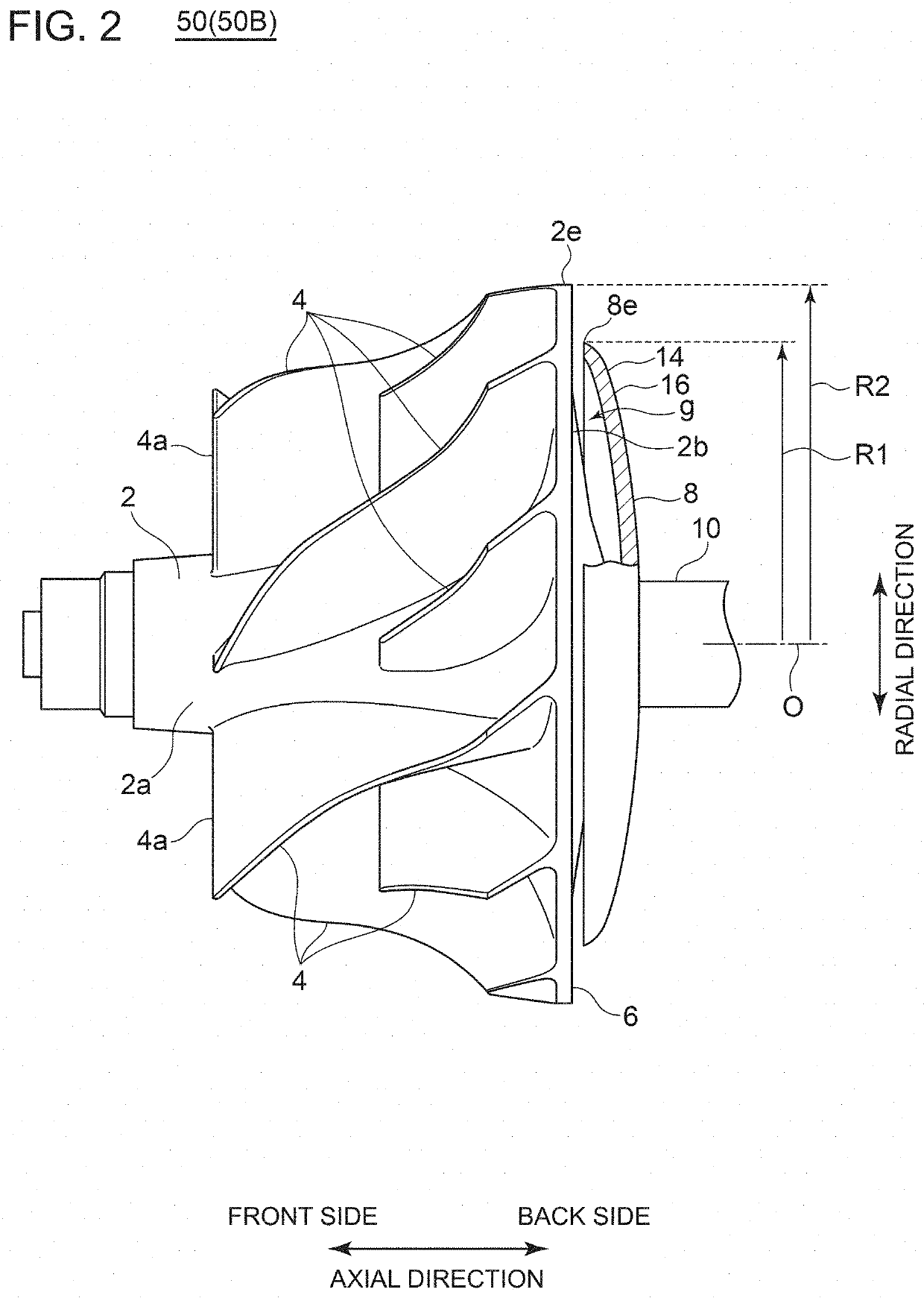
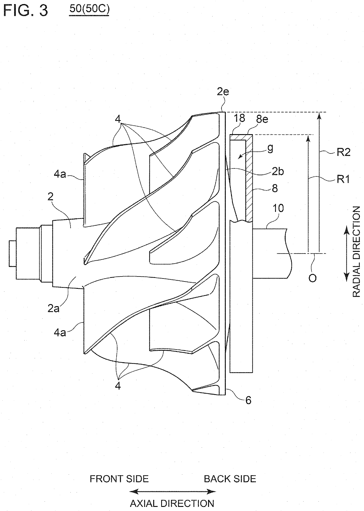
[0047]Embodiments of the present invention will now be described in detail with reference to the accompanying drawings. It is intended, however, that unless particularly identified, dimensions, materials, shapes, relative positions and the like of components described in the embodiments shall be interpreted as illustrative only and not intended to limit the scope of the present invention.

[0048]For instance, an expression of relative or absolute arrangement such as “in a direction”, “along a direction”, “parallel”, “orthogonal”, “centered”, “concentric” and “coaxial” shall not be construed as indicating only the arrangement in a strict literal sense, but also includes a state where the arrangement is relatively displaced by a tolerance, or by an angle or a distance whereby it is possible to achieve the same function.

[0049]For instance, an expression of an equal state such as “same”“equal” and “uniform” shall not be construed as indicating only the state in which the feature is strict...


PUM


Abstract

A compressor impeller includes: a compressor impeller body portion including a boss portion and a plurality of vane portions disposed at intervals in a circumferential direction on a peripheral surface of the boss portion; and a heat shield portion disposed on a side of a back surface of the boss portion and configured to rotate with the compressor impeller body portion

Description

TECHNICAL FIELD[0001]The present disclosure relates to a compressor impeller.BACKGROUND ART[0002]Normally, the compressor impeller includes a boss portion, and a plurality of vane portions disposed at intervals in the circumferential direction on the peripheral surface of the boss portion.[0003]FIG. 7 is a diagram showing the distribution of air temperature on the front side (the side where the vanes 004 are provided) of the boss portion 002 of the compressor impeller 050, during operation of the compressor used for the turbocharger. FIG. 8 is a diagram showing the distribution of air temperature in the gap on the back side (the gap in the axial direction between the back side of the boss portion and the stationary portion of the casing or the like) of the boss portion 002 of the compressor impeller 050, during operation of the compressor. FIG. 9 is a diagram showing the distribution of the metal temperature of the compressor impeller 050 during operation of the compressor. FIGS. 7 ...

Claims


Application Information

Patent Timeline
Patent Type & Authority Applications(United States)
IPC IPC(8): F04D29/58F04D29/28F04D29/02
CPCF04D29/284F05C2251/048F05D2250/141F05D2240/15F04D29/5853F04D29/023
Inventor YOKOYAMA, TAKAOFUJITA, YUTAKA
Owner MITSUBISHI HEAVY IND ENGINE & TURBOCHARGER LTD
Why Eureka
Try Eureka