Systems and methods for welding

a technology of systems and methods, applied in the field of laser welding, can solve the problems of preventing weld defects, reducing the time that a welded part is irradiated by a laser, and significantly so as to achieve the effect of preventing weld defects, reducing the time that a welded part is irradiated by a laser, and reducing the amount o

Inactive Publication Date: 2018-05-24
TOYOTA MOTOR EUROPE +1
View PDF0 Cites 0 Cited by
  • Summary
  • Abstract
  • Description
  • Claims
  • Application Information

AI Technical Summary

Benefits of technology

[0020]By providing such a method, the time that a welded part is irradiated by a laser can be substantially reduced, e.g., by up to 400 percent, and therefore, temperature increases in surrounding areas of the welded object due to prolonged heating can be significantly limited. By limiting such temperature increases, vaporization of an electrolyte inside a battery, for example, can be limited or even eliminated, thus preventing weld defects due to such effects.

Problems solved by technology

By providing such a configuration, the time that a welded part is irradiated by a laser can be substantially reduced, e.g., by up to 400 percent, and therefore, temperature increases in surrounding areas of the welded object due to prolonged heating can be significantly limited.

Method used


Image

  • Systems and methods for welding
  • Systems and methods for welding
  • Systems and methods for welding

Examples


Embodiment Construction

[0035]Reference will now be made in detail to exemplary embodiments of the disclosure, examples of which are illustrated in the accompanying drawings. Wherever possible, the same reference numbers will be used throughout the drawings to refer to the same or like parts.

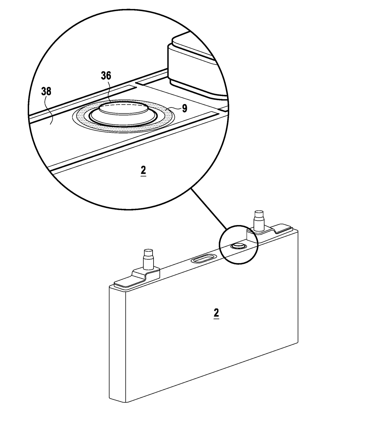
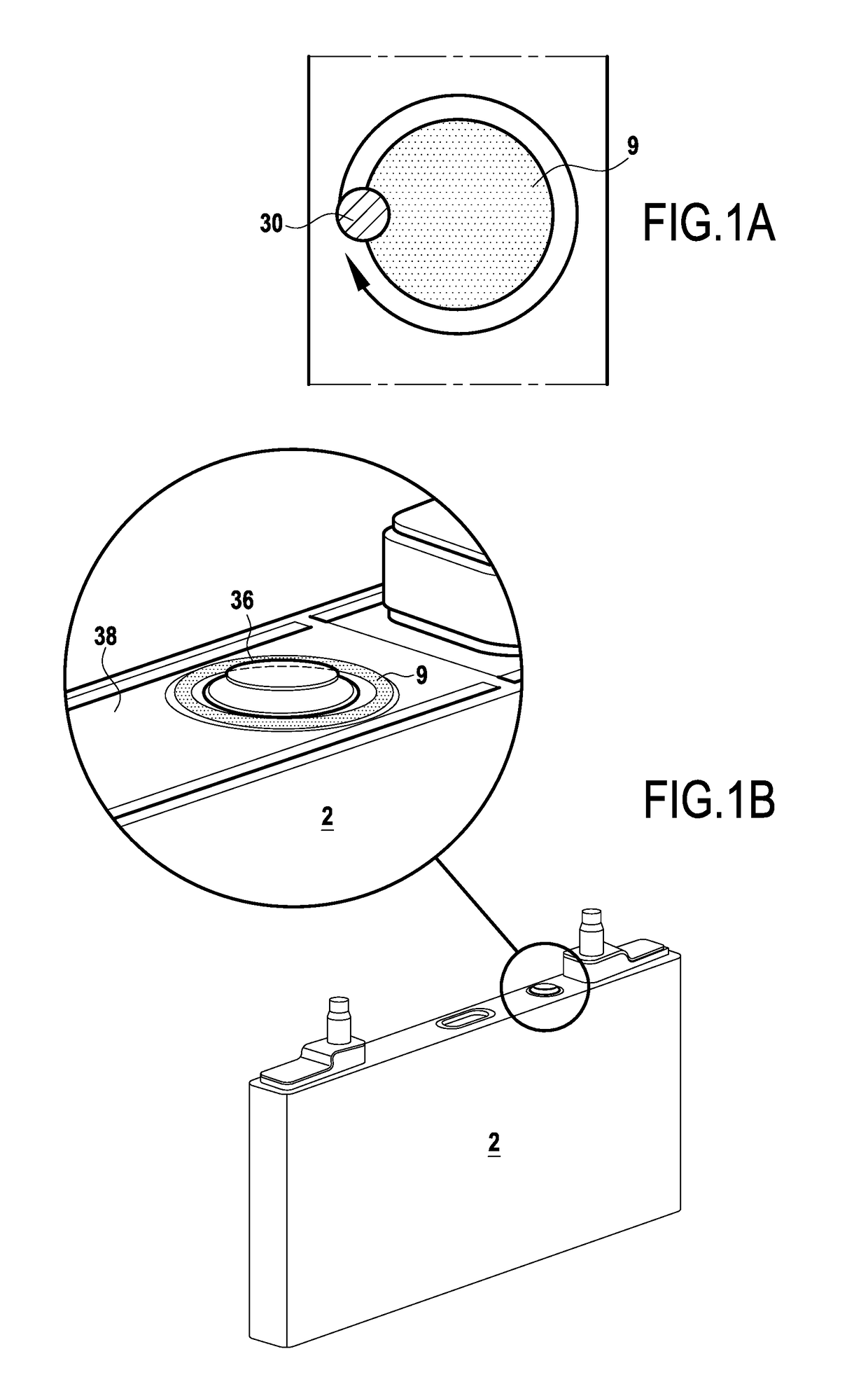
[0036]FIG. 1A shows a prior art welding technique for welding an electrolyte fill-hole cap 36 to a cover 38 of a battery as shown in FIG. 1B. As described above, a single point laser is used, and this single point is scanned around 360 degrees of the circumference of the part to be welded. During such welding, excess heat is transferred to the surrounding areas and electrolyte vaporization can occur.

[0037]When electrolyte vaporization occurs, internal pressure build up can cause significant weld defects. These defects can lead to later problems with the battery.

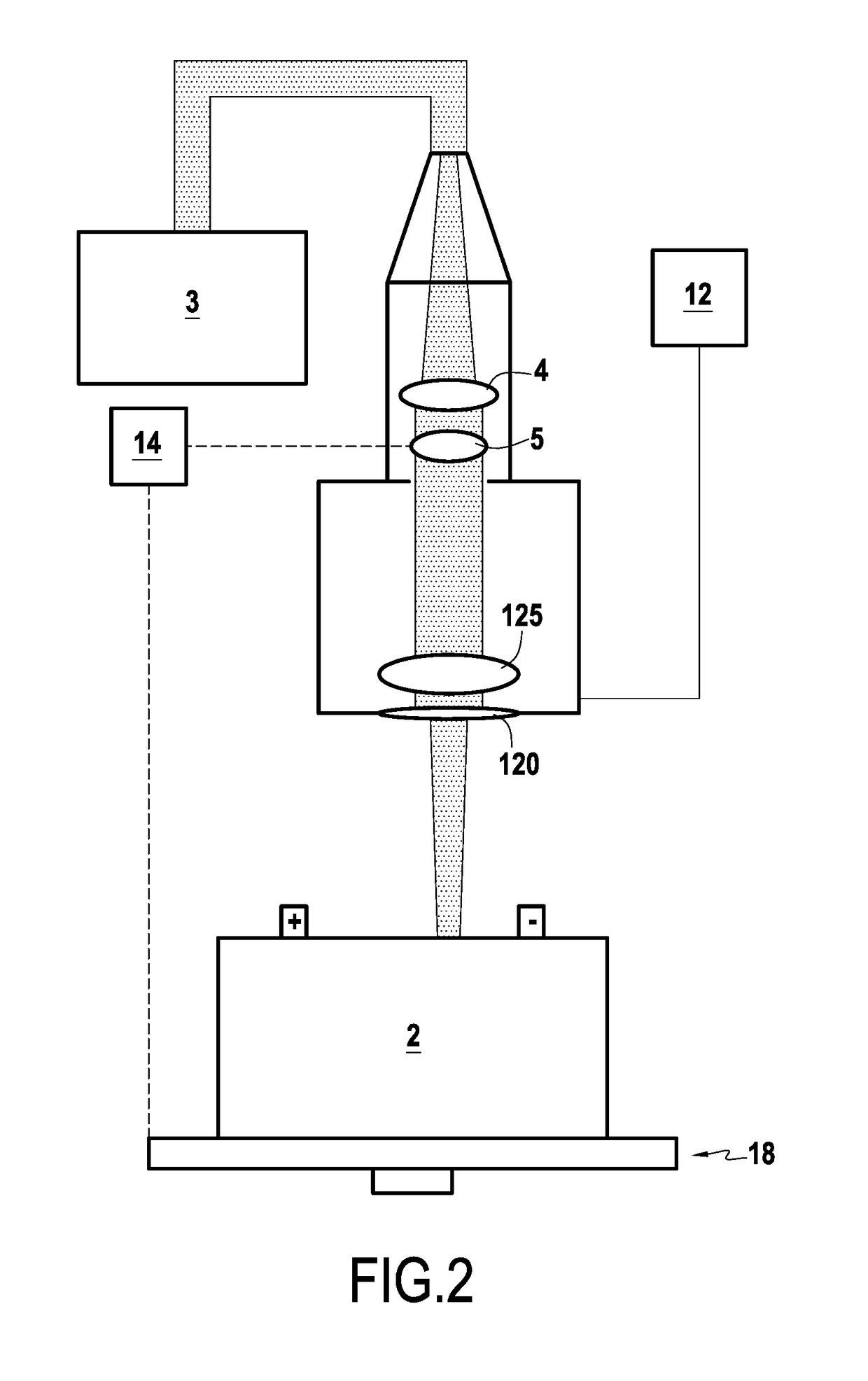
[0038]FIG. 2 shows an exemplary welding system 1 configured to remedy the above problems according to embodiments of the present disclosure. Welding system 1 ma...


PUM

PropertyMeasurementUnit
angleaaaaaaaaaa
angleaaaaaaaaaa
heataaaaaaaaaa

Abstract

A laser welding system is provided. The laser welding system includes a laser source configured to produce a laser beam, a beam modifier configured to split the laser beam into at least two heat source points positioned at a predetermined angle relative to one another along a diagonal intersecting and radially equidistant from a center of a circular weld line, the circular weld line being concentric with an object to be welded, a rotation unit configured to cause rotation of the at least one group of two heat source points or the object to be welded, and a controller configured to control the rotation unit to cause the at least one group of two heat source points to scan substantially all of the circular weld line.

Description

FIELD OF THE DISCLOSURE[0001]The present disclosure is related to systems and methods for welding, and more particularly to laser welding using optical elements to form multiple heat source points.BACKGROUND OF THE DISCLOSURE[0002]In manufacturing of electronic devices, e.g., batteries, fuel cells, etc., component design often involves various pieces (e.g., two or more thin metal sheets) being assembled together by welding.[0003]Typically, metal sheets are positioned together and placed on a welding support. A welding device (e.g., laser, electron beam / plasma, arc-welder, and / or other similar devices) can then be used to perform a welding operation.[0004]For example, when closing a filling hole of a battery (e.g., a lithium-ion battery), the inner portion of the battery may be assembled or placed within the case, the cover welded in place, electrolyte provided via the filling hole, and an the filling hole in the battery case is then closed by laser welding a cap to cover the hole.[0...

Claims


Application Information

Patent Timeline
Patent Type & Authority Applications(United States)
IPC IPC(8): B23K26/20B23K26/08H01M2/04H01M2/36H01M50/147H01M50/627H01M50/645
CPCB23K26/206B23K26/0823H01M2/0404H01M2/361H01M2/365Y02E60/10H01M50/147H01M50/645H01M50/627
Inventor TSUKUI, AKIRANAKAYAMA, TAKAYUKI
Owner TOYOTA MOTOR EUROPE
Why Eureka
Try Eureka