Film forming device

a technology of film forming and sealing parts, which is applied in the direction of vacuum evaporation coatings, electrolysis components, coatings, etc., can solve the problems of deterioration of seal materials between the closing members and the evaporation source, and achieve the effect of preventing damage to seal members and the like which maintain a vacuum near the auxiliary electrode, and reducing the risk of damag

Active Publication Date: 2016-01-14
TOYOTA JIDOSHA KK
View PDF6 Cites 1 Cited by
  • Summary
  • Abstract
  • Description
  • Claims
  • Application Information

AI Technical Summary

Benefits of technology

[0016]The auxiliary electrode may include a gas passage which supplies process gas to the internal space of the cylindrical evaporation source. As a result, the gas passage is disposed along the inner wall surface of the cylindrical evaporation source such that electrons are likely to flow thereto, and the auxiliary electrode and peripheral members thereof which are likely to be heated to a relatively high temperature are actively cooled by the process gas, which can suppress a temperature increase. That is, the gas passage for the supply of the process gas functions as the internal cooling structure of the closing members and the auxiliary electrode. Accordingly, the thermal deformation of the auxiliary electrode and the peripheral members thereof can be efficiently suppressed. In addition, the damage of a seal member and the like which maintain a vacuum near the auxiliary electrode can be prevented. For example, the heat resistance temperature of a seal member such as an O-ring or a gasket can be decreased.
[0017]In addition, the auxiliary electrode may have a gas discharge hole of the gas passage near an arc spot of the cylindrical evaporation source such that the process gas may be supplied to a region near the arc spot of the evaporation source. As a result, in the internal space of the cylindrical evaporation source in a high-vacuum state, plasma can be efficiently generated in the region near the arc spot to make arc discharge stable.
[0018]Here, for example, when Ti or a Ti alloy is used as the material of the evaporation source, process gas containing C2H2 (acetylene) may be used. As a result, TiC (titanium carbide) having a higher melting point than that of Ti is likely to be produced on the inner wall surface of the cylindrical evaporation source. Due to arc discharge, not only ions of a metal material of the cylindrical evaporation source but also droplets which are molten metal particles are discharged to the internal space of the cylindrical evaporation source. When these droplets are incorporated into the film on the surface of the workpiece, the surface roughness of the film may deteriorate. However, when TiC having a higher melting point than that of Ti is produced on the inner wall surface of the cylindrical evaporation source, the particle size of droplets produced from TiC can be made to be less than that of droplets produced from Ti. Accordingly, the surface roughness of the film on the workpiece can be decreased.
[0019]A shield member may be disposed between the cylindrical evaporation source and the auxiliary electrode so as to prevent discharge therebetween. When the auxiliary electrode as the anode is disposed along the inner wall surface of the cylindrical evaporation source as the cathode, the anode and the cathode are close enough to each other to cause direct discharge. As a result, ions of a metal material constituting the cylindrical evaporation source may be inefficiently deposited on the surface of the workpiece. Therefore, by the shield member preventing discharge between the cylindrical evaporation source and the auxiliary electrode, ions of a metal material constituting the cylindrical evaporation source can be efficiently deposited on the surface of the workpiece.
[0020]Here, the shield member may be insulated from the cylindrical evaporation source and the auxiliary electrode. For example, the shield member may be fixed to the auxiliary electrode, the cylindrical evaporation source, or the closing members through an insulating member having electrical insulating properties. Here, the shield member is not grounded. As a result, the shield member is electrically insulated from the cylindrical evaporation source and the auxiliary electrode such that the potential can be made to be the same as that of plasma of the internal space of the cylindrical evaporation source, and discharge between the cylindrical evaporation source and the auxiliary electrode can be efficiently prevented.
[0021]In the film forming device according to the aspect, the auxiliary electrode functions as the anode as in the case of the closing members. In addition, if the auxiliary electrode is not provided, the closing members receive a portion of the flowing electrons. As a result, as compared to a film forming device of the related art, the amount of electrons flowing to the closing members decreases, the amount of a current generated in the closing members decreases, and the amount of Joule heat generated in the closing members can be suppressed.

Problems solved by technology

In this case, for example, a seal material between the closing members and the evaporation source may deteriorate due to the heat.

Method used


Image

  • Film forming device
  • Film forming device
  • Film forming device

Examples


Embodiment Construction

[0033]Hereinafter, a film forming device according to the invention will be described based on an embodiment with reference to the drawings.

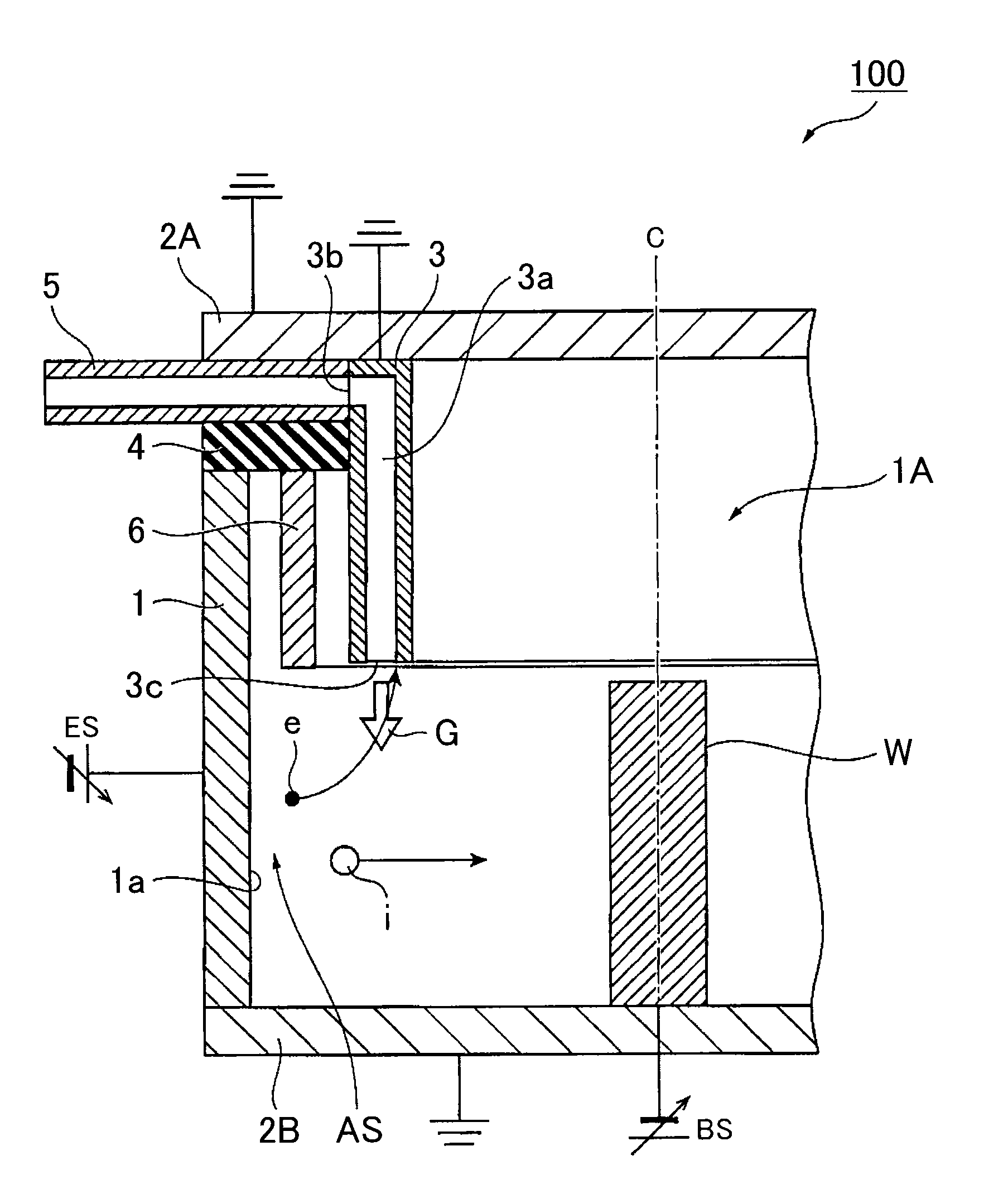
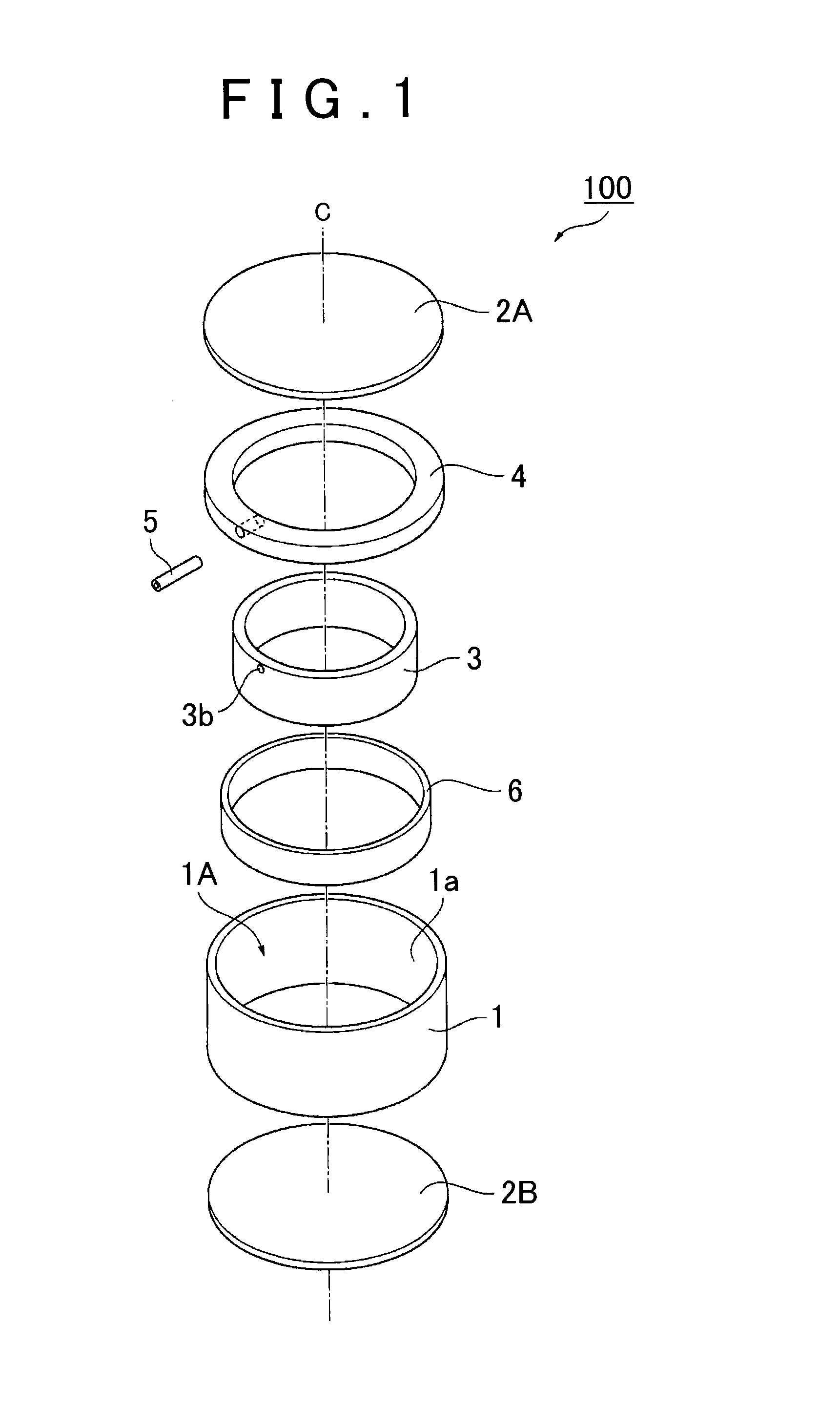
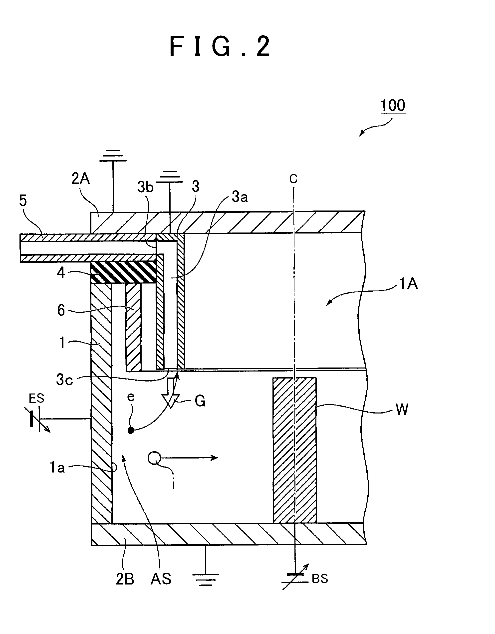
[0034]FIG. 1 is an exploded perspective view schematically showing an embodiment of a film forming device 100 according to the invention. FIG. 2 is an enlarged cross-sectional view showing a part of the film forming device 100 shown in FIG. 1.

[0035]The film forming device 100 according to the invention includes: a cylindrical evaporation source 1 that has an internal space 1A for accommodating a workpiece W; and closing members 2A, 2B that close the internal space 1A, in which ions i which are discharged from the evaporation source 1 by arc discharge are deposited on a surface of the workpiece W to form a film thereon. The film forming device 100 according to the invention is mostly characterized in that an auxiliary electrode 3 is disposed along the inner wall surface 1a of the evaporation source 1, in which the auxiliary electrode 3 is grounde...


PUM

PropertyMeasurementUnit
currentaaaaaaaaaa
voltageaaaaaaaaaa
voltageaaaaaaaaaa

Abstract

A film forming device includes a cylindrical evaporation source, closing members, and an auxiliary electrode. The cylindrical evaporation source is configured to accommodate a workpiece in an internal space of the cylindrical evaporation source. The cylindrical evaporation source is configured to discharge ions from the cylindrical evaporation source by arc discharge such that the ions are deposited on a surface of the workpiece. The closing members close the internal space. The auxiliary electrode is disposed along an inner wall surface of the cylindrical evaporation source. The auxiliary electrode is configured to be grounded or to be applied with a positive voltage such that electrons of the internal space flow to the auxiliary electrode.

Description

INCORPORATION BY REFERENCE[0001]The disclosure of Japanese Patent Application No. 2014-143532 filed on Jul. 11, 2014 including the specification, drawings and abstract is incorporated herein by reference in its entirety.BACKGROUND OF THE INVENTION[0002]1. Field of the Invention[0003]The present invention relates to a film forming device which is used for, for example, an arc ion plating method.[0004]2. Description of Related Art[0005]An arc ion plating (hereinafter, abbreviated as “AIP”) method is an ion plating method in which a solid material is evaporated using vacuum arc discharge. In this method, the ionization rate of the evaporated material is high, and a film having superior adhesion can be formed.[0006]In the AIP method, vacuum arc discharge is caused to occur between a target (evaporation source), which is a cathode, and an anode in a vacuum so as to evaporate and ionize a material on a target surface, and ions are deposited on a workpiece surface to which a negative bias ...

Claims


Application Information

Patent Timeline
Patent Type & Authority Applications(United States)
IPC IPC(8): H01J37/32C23C14/32
CPCH01J37/32559H01J37/3244C23C14/325H01J37/32055H01J37/34
Inventor SATO, TAKAYASUSATO, YOJITACHIBANA, KAZUTAKA
Owner TOYOTA JIDOSHA KK
Why Eureka
Try Eureka