Adiabatic Concrete Calorimeter and Method

a concrete calorimeter and adiabatic technology, applied in the direction of calorimeters, instruments, material heat development, etc., can solve problems such as introducing errors into the testing process

Active Publication Date: 2020-05-28
MCCALL W CALVIN
View PDF0 Cites 7 Cited by
  • Summary
  • Abstract
  • Description
  • Claims
  • Application Information

AI Technical Summary

Benefits of technology

[0017]In accordance with another aspect of the invention, the plurality of temperature sensors consist of detectors selected from the group consisting of resistance temperature detectors, thermistors and thermocouples.
[0018]In accordance with another aspect of the invention, the plurality of temperature sensors comprise resistance temperature detectors spaced in vertical and circumferential relation to each other on inner surface of the test cylinder container, and on a cover and bottom of the test cylinder container.

Problems solved by technology

This introduces error into the testing process.

Method used


Image

  • Adiabatic Concrete Calorimeter and Method
  • Adiabatic Concrete Calorimeter and Method
  • Adiabatic Concrete Calorimeter and Method

Examples


Embodiment Construction

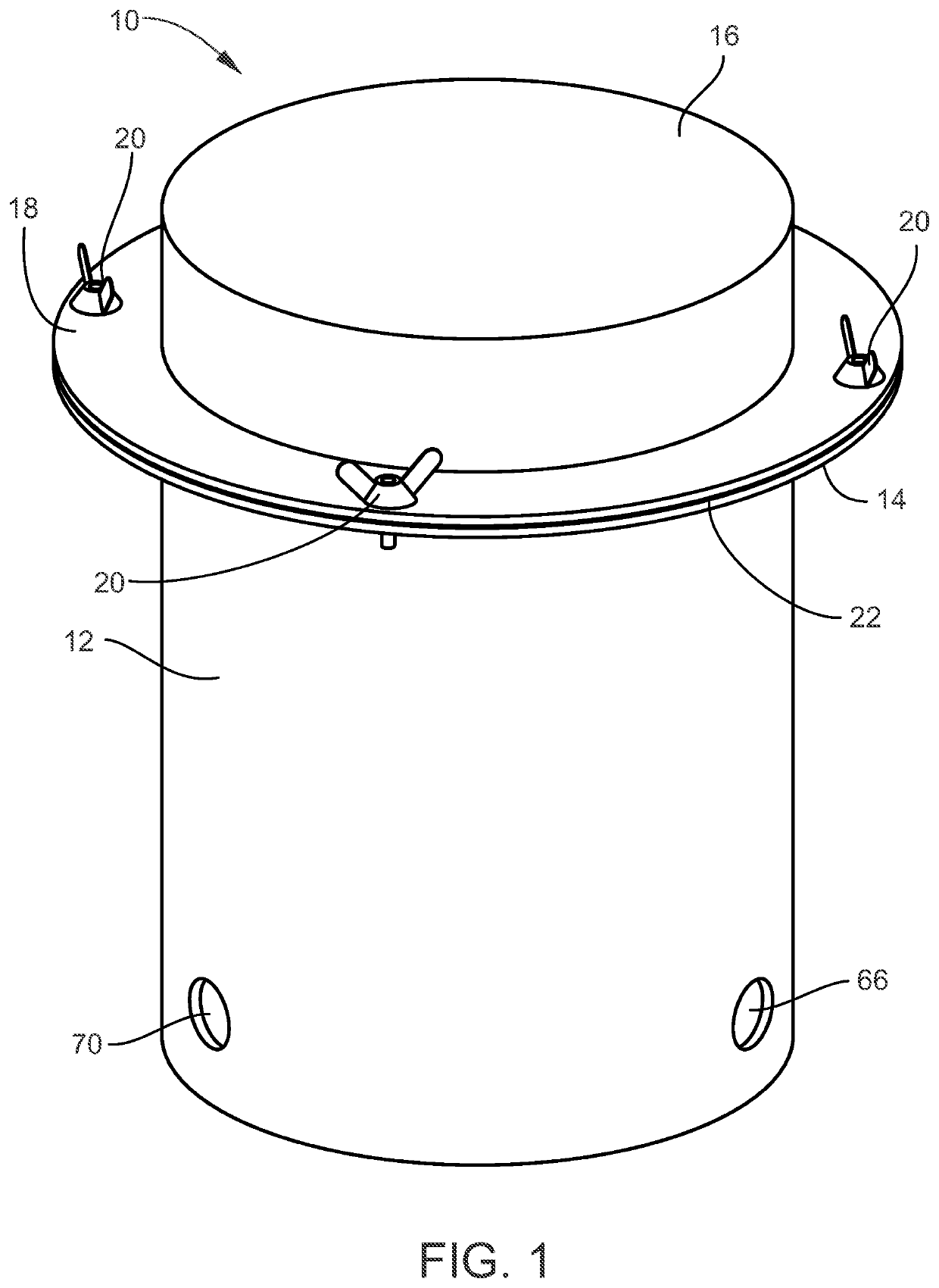
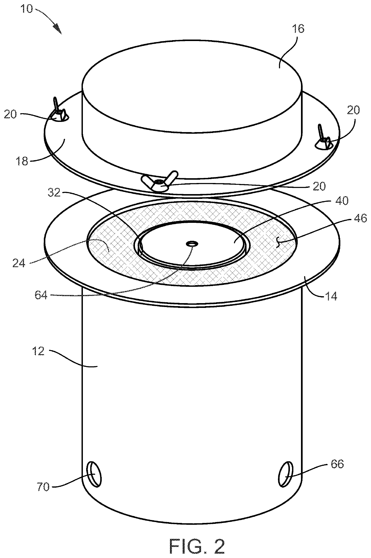
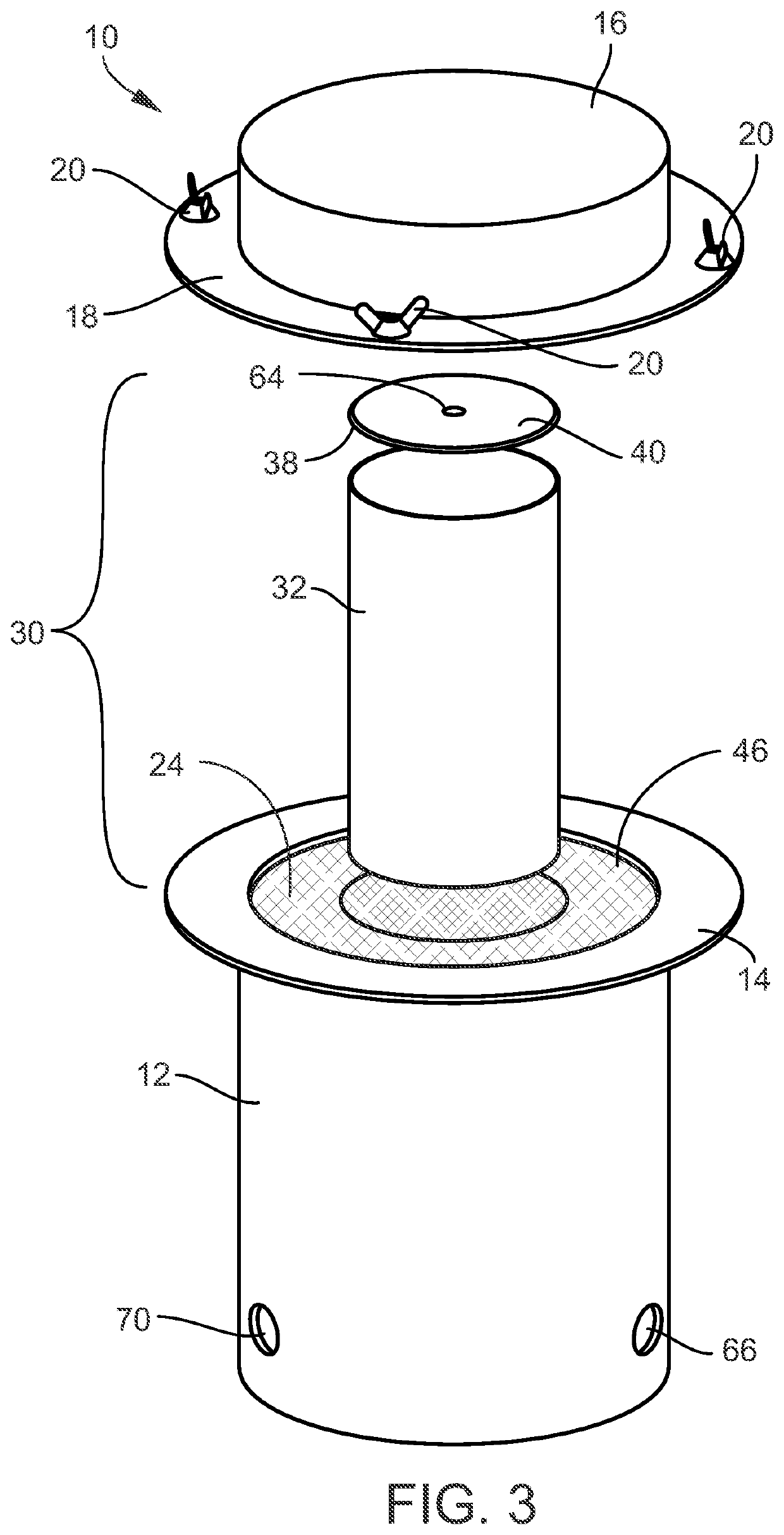
[0033]Referring now to the Figures, an adiabatic concrete calorimeter 10 is shown, and includes a stainless steel thermal chamber 12 having an outwardly-extending flange 14 surrounding its top opening that is adapted to receive and support a removable lid 16. The lid 16 has an outwardly-extending flange 18 secured to the flange 14 of the thermal chamber 12 by a series of spaced-apart bolt and wing-nut assemblies 20. A vapor barrier sheet 22 is positioned between the top surface of the thermal chamber flange 14 and the bottom surface of the lid flange 18 and held in a sealing condition by the tightened wing nut assemblies 20 that force the thermal chamber flange 14 and the lid flange 18 into intimate sealing contact. The thermal chamber 12 includes a void 24 into which a heat well subassembly 30 is placed.

[0034]The heat well subassembly 30 includes a test cylinder container 32 wrapped with flexible heating elements 34 in the form of a high temperature silicone over-molded resistive t...


PUM

PropertyMeasurementUnit
90 degree anglesaaaaaaaaaa
heightaaaaaaaaaa
thicknessaaaaaaaaaa

Abstract

An adiabatic concrete calorimeter includes a thermal chamber and a heat well subassembly for being positioned in the thermal chamber. The heat well subassembly includes a test cylinder container and a test cylinder mold adapted to be positioned in the test cylinder container for defining the shape of a concrete test specimen formed in the test cylinder mold. Temperature sensors determine the temperature of the concrete test specimen, and transmit temperature data from the temperature sensors to a controller. Electrically-energized heaters are positioned on a surface of the test cylinder container for applying heat to the test cylinder container. A controller determines heat loss of the concrete test specimen and outputs data to the heaters whereby the heaters supply heat to the concrete test specimen sufficient to compensate for heat losses to an ambient environment and maintain the heat of hydration of the concrete test specimen.

Description

CROSS-REFERENCE TO RELATED PATENT APPLICATIONS[0001]This patent application is a continuation-in-part non-provisional application which claims the full benefit of U.S. Provisional Patent Application No. 62 / 692,989 filed on Jul. 2, 2018, entitled “Adiabatic Concrete Calorimeter and Method”, the contents of which are incorporated by reference herein, and U.S. Utility patent application Ser. No. 16 / 502,575, filed Jul. 3, 2019, the contents of which are incorporated by reference herein.TECHNICAL FIELD AND BACKGROUND OF INVENTION[0002]This application relates to an apparatus and method of directly measuring the quantity of heat and the rate of heat generation from a concrete specimen. As concrete elements gain strength due to a chemical process, the heat that is generated from this chemical process is typically referred to as the “heat of hydration.” For the purposes of this application “heat of hydration” can be defined as the heat that is generated from a specific concrete mixture over...

Claims


Application Information

Patent Timeline
Patent Type & Authority Applications(United States)
IPC IPC(8): G01K17/04G01N25/20G01N33/38
CPCG01N25/20G01N33/383G01K17/04
Inventor MCCALL, W. CALVIN
Owner MCCALL W CALVIN
Why Eureka
Try Eureka