
Synchronous operation display system and non-transitory computer readable medium

Inactive Publication Date: 2020-05-28
INVENTEC PUDONG TECH CORPOARTION +1
View PDF0 Cites 1 Cited by
  • Summary
  • Abstract
  • Description
  • Claims
  • Application Information

AI Technical Summary

Benefits of technology

The synchronous operation display system helps users save time by automating unnecessary manual operations. This system allows for convenient design and saving.

Problems solved by technology

However, most of the design guidelines and manuals only list the formulas or parameters that may be used in the design and the schematic diagrams of the applications without showing actual results.
Therefore, when engineers study these materiel, the engineers are only able to manually copy formulas or data into the application program, resulting in waste of time.

Method used


Image

  • Synchronous operation display system and non-transitory computer readable medium
  • Synchronous operation display system and non-transitory computer readable medium
  • Synchronous operation display system and non-transitory computer readable medium

Examples


Embodiment Construction

[0018]All terms used in this disclosure have their ordinary meanings. The above vocabulary is defined in the commonly used dictionary, and any examples of the use of the vocabulary discussed herein are included in the description of the specification, and are not intended to limit the scope and meaning of the disclosure. As such, the present disclosure is not limited to the various embodiments shown in this specification.

[0019]As used herein, “coupled” or “connected” may mean that two or more elements are in direct physical or electrical contact with each other, or indirectly in physical or electrical contact with each other. It can also mean that two or more components operate or act on each other.

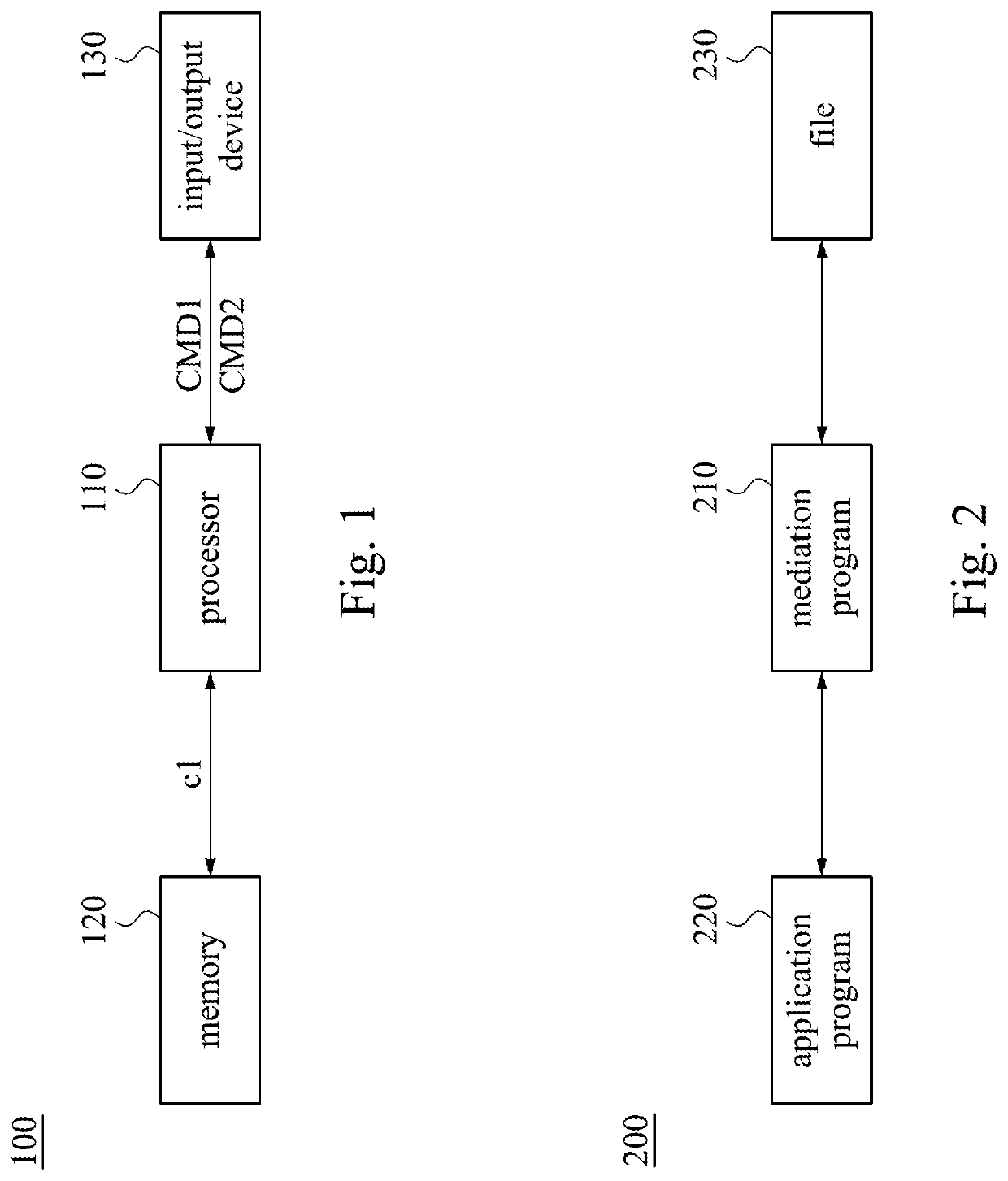
[0020]Referring to FIG. 1, FIG. 1 is a schematic diagram of a synchronous operation display system 100 according to some embodiments of the present disclosure. In different applications, the synchronous operation display system 100 can be a device (e.g., personal computer, tablet computer...


PUM


Abstract

A system for synchronous operation display is operated in at least one computer. The system for synchronous operation display includes an input / output (I / O) device, a memory, and a processor. The I / O device is configured to display a screen and receive an operation input. The memory store includes computer code, application programs, and files. The processor is coupled to the I / O device and the memory. The processor is configured to execute the computer program code, in order to provide an object design screen, and display the design specification in the corresponding window.

Description

CROSS-REFERENCE TO RELATED APPLICATION[0001]This application claims priority to China Application Serial Number 201811416518.8, filed Nov. 26, 2018, which is herein incorporated by reference in its entirety.BACKGROUNDTechnical Field[0002]The present disclosure relates to a synchronous operation display system and a non-transitory computer readable medium, and in particular to a display system for simultaneous operation of files and applications.Description of Related Art[0003]When a user makes designs for objects via an application program, it generally requires studying relevant guidelines, manuals, and specified chapters thereof at first, in order to make the designs via the application program with reference to related designing parameters or methods. However, most of the design guidelines and manuals only list the formulas or parameters that may be used in the design and the schematic diagrams of the applications without showing actual results. Therefore, when engineers study th...

Claims


Application Information

Patent Timeline
IPC IPC(8): G06F17/50G06F3/0481G06F3/0484G06F3/14
CPCG06F2111/20G06F3/0481G06F30/00G06F3/04842G06F2203/04803G06F3/14G06F8/10G06F30/12
Inventor CHEN, CHENG-HSINLIN, CHUN-HUNG
Owner INVENTEC PUDONG TECH CORPOARTION
Learn More