
In-vehicle camera system

a camera system and vehicle technology, applied in the field of vehicle camera systems, can solve the problems of not being able to continuously execute such processing, blown out highlights, etc., and achieve the effect of avoiding unnecessary aperture control of the near camera

Active Publication Date: 2020-05-28
TOYOTA JIDOSHA KK
View PDF4 Cites 2 Cited by
  • Summary
  • Abstract
  • Description
  • Claims
  • Application Information

AI Technical Summary

Benefits of technology

The patent describes an in-vehicle camera system that can capture images in front of a vehicle and adjust the aperture to prevent blown out highlights caused by sudden illumination changes. The system includes a determining unit that detects abnormal illumination of the image captured by the far camera and an aperture control unit that adjusts the aperture of the near camera to capture the image without blown out highlights. The system can also determine if the illumination of the image captured by the far camera is normalized during travel and cancel the aperture control over the near camera to avoid unnecessary adjustments. The technical effect of the in-vehicle camera system is to capture images with the near camera in a situation where there is a sudden illumination change, such as when the vehicle leaves a tunnel, while avoiding blown out highlights and ensuring appropriate aperture control.

Problems solved by technology

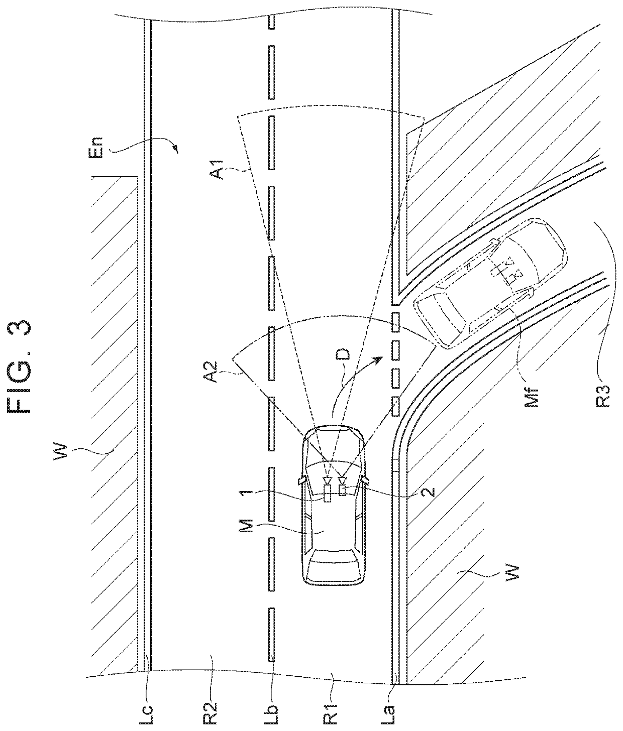
Incidentally, it is known that blown out highlights, or the like, occur as a result of a delay of aperture change of the in-vehicle camera when there occurs a sudden illumination change, for example, after the vehicle leaves a tunnel.
However, it is not easy to constantly execute such processing.
With this in-vehicle camera system, even when it is determined that the illumination of the image captured by the far camera is abnormal, there is still a time difference until the illumination of an image that is captured by the near camera becomes abnormal.

Method used


Image

  • In-vehicle camera system
  • In-vehicle camera system
  • In-vehicle camera system

Examples


Embodiment Construction

[0016]Hereinafter, an embodiment of the disclosure will be described with reference to the accompanying drawings.

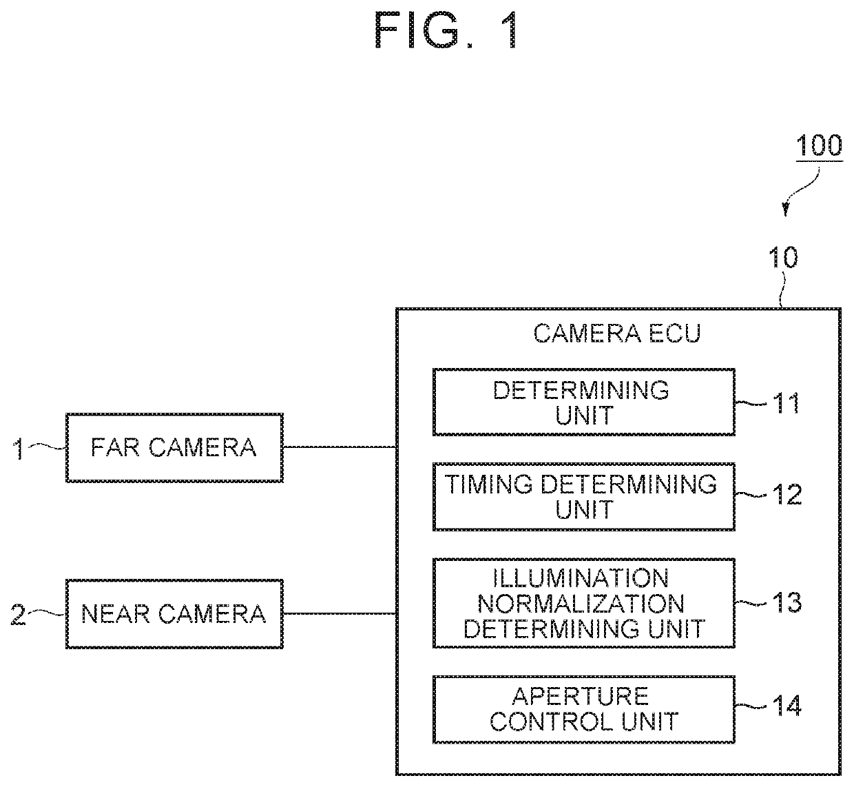
[0017]FIG. 1 is a block diagram that shows an in-vehicle camera system according to the embodiment. The in-vehicle camera system 100 shown in FIG. 1 is a camera system that is mounted on a vehicle, such as a passenger automobile, and that captures an image around the vehicle.

Configuration of In-Vehicle Camera System

[0018]As shown in FIG. 1, the in-vehicle camera system 100 includes a far camera 1, a near camera 2, and a camera electronic control unit (ECU) 10. The far camera 1 and the near camera 2 are cameras that capture an image ahead of the vehicle. The far camera 1 and the near camera 2 are provided, for example, on the back side of the windshield of the vehicle. The far camera 1 and the near camera 2 may be separate cameras or may be a combination camera in which part of a body is shared.

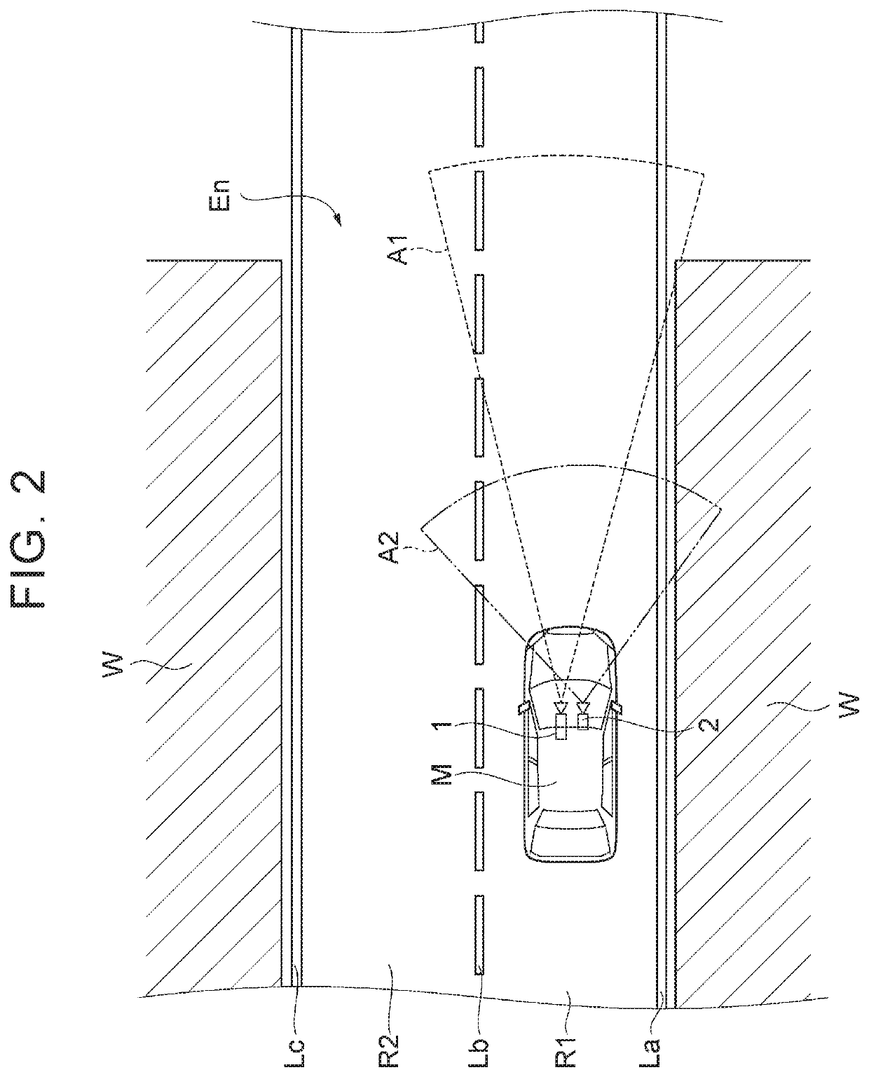
[0019]FIG. 2 is a plan view for illustrating an example of the far camera and n...


PUM


Abstract

An in-vehicle camera system including a far camera and a near camera, both of which capture an image ahead of a vehicle, includes a determining unit configured to, during travel of the vehicle, determine whether an illumination of an image captured by the far camera is abnormal as a result of an illumination change ahead of the vehicle, and an aperture control unit configured to, when the determining unit determines that the illumination of the image captured by the far camera is abnormal, execute aperture control over the near camera.

Description

CROSS-REFERENCE TO RELATED APPLICATIONS[0001]This application claims priority to Japanese Patent Application No. 2018-222317 filed on Nov. 28, 2018, which is incorporated herein by reference in its entirety including the specification, drawings and abstract.BACKGROUND1. Technical Field[0002]The disclosure relates to an in-vehicle camera system.2. Description of Related Art[0003]Hitherto, Japanese Patent No. 6176028 (JP 6176028 B) is known as a technical document on image recognition of an in-vehicle camera. This document describes a system that generates a plurality of pieces of individual image data with different brightness from one image data captured with an in-vehicle camera oriented ahead of a vehicle with the use of a plurality of filters and that, even when there are blown out highlights or blocked up shadows in any one of the pieces of individual image data, recognizes an image of an object, such as a preceding vehicle, by using the pieces of individual image data where the...

Claims


Application Information

Patent Timeline
Patent Type & Authority Applications(United States)
IPC IPC(8): H04N5/235H04N5/247H04N5/238H04N23/75H04N23/90
CPCH04N5/247H04N5/238H04N5/2351H04N7/18H04N7/181B60R2300/105B60R2300/10H04N23/75H04N23/71H04N23/90
Inventor YAMAOKA, MASAAKIKADOTANI, NAOTOSHI
Owner TOYOTA JIDOSHA KK
Learn More