Relay-server arranged to carry out communications between communication terminals on different LANS

a communication terminal and relay server technology, applied in the direction of data switching by path configuration, digital transmission, data switching network, etc., can solve the problems of increased large load on the server, so as to reduce the burden of account control and suppress load

Active Publication Date: 2013-06-25
MURATA MASCH LTD
View PDF156 Cites 0 Cited by
  • Summary
  • Abstract
  • Description
  • Claims
  • Application Information

AI Technical Summary

Benefits of technology

[0012]In order to solve the problems described above, preferred embodiments of the present invention provide a technique capable of carrying out communications between communication terminals on different LANs while realizing reduction in the burden of account control, suppression in load imposed on a server and facilitation of the account control.
[0017]With this configuration, the relay servers control the accounts of the communication terminals in a distributed manner, which makes it possible to lessen a load imposed on the external server performing account control. Further, each communication terminal accesses the relay server, thereby acquiring account information of another communication terminal on a separate local area network.
[0018]In addition, the relay server holds the account information acquired by the exchange with the another relay server while bringing the account information into correspondence with the account information of the another relay server. Thus, an account can be freely provided to each local area network. Therefore, collective control of accounts becomes unnecessary in the entire system, so that the account can be readily controlled.

Problems solved by technology

If communications are carried out among plural LANs using the SIP, plural pieces of account information are registered in the SIP-server, leading to an increase in load imposed on the server.
Consequently, a large load has been imposed on the server.
When the respective communication terminals access the server to acquire such account information, the load imposed on the server becomes larger.
In other words, each LAN cannot obtain an account freely.
Consequently, a degree of freedom inconveniently becomes small in terms of network control.

Method used


Image

  • Relay-server arranged to carry out communications between communication terminals on different LANS
  • Relay-server arranged to carry out communications between communication terminals on different LANS
  • Relay-server arranged to carry out communications between communication terminals on different LANS

Examples


Embodiment Construction

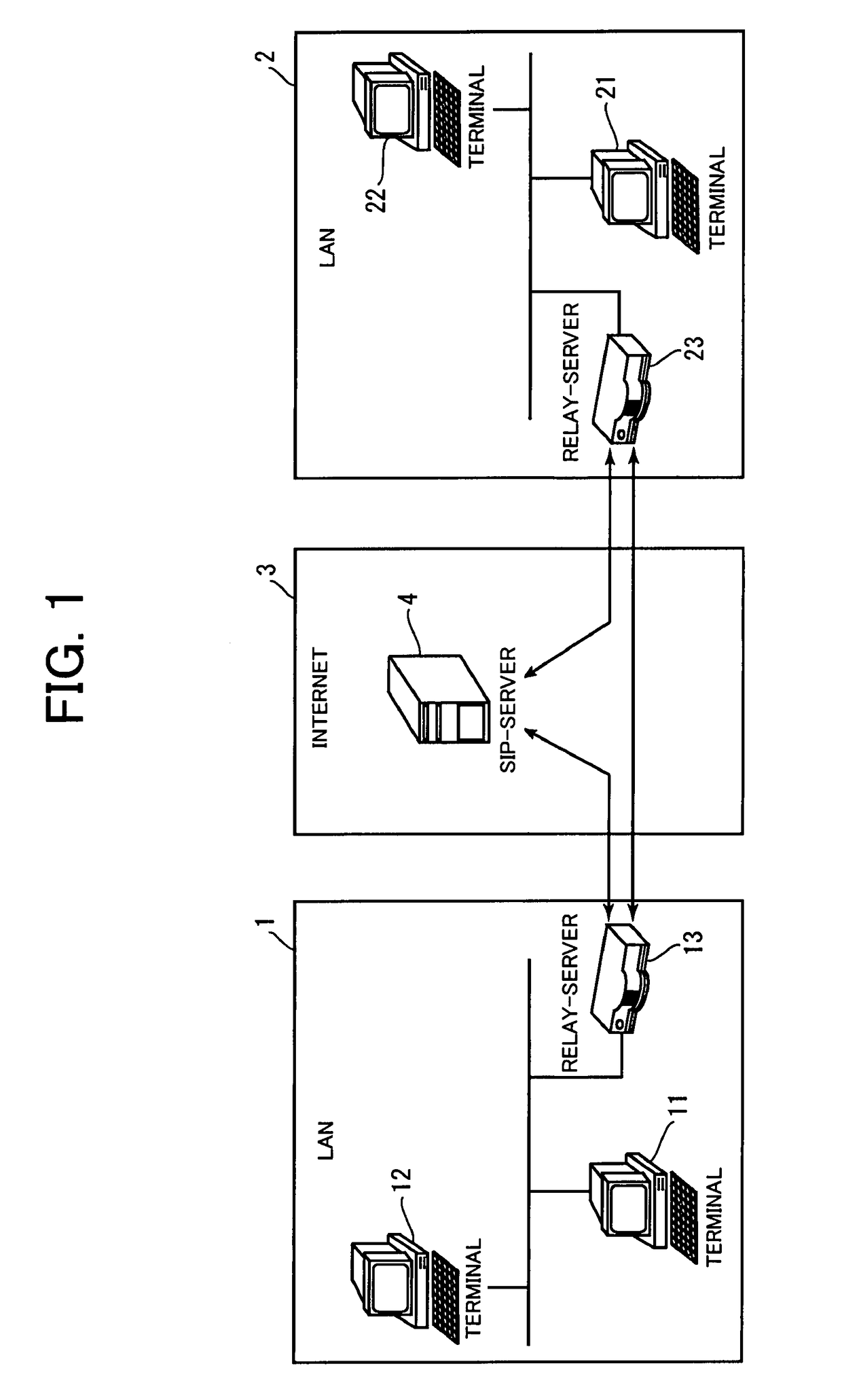
[0027]Hereinafter, description will be provided of preferred embodiments of the present invention with reference to the drawings. FIG. 1 illustrates a general configuration of a communication system according to a preferred embodiment of the present invention. This communication system preferably includes the Internet 3 and two LANs 1, 2 each connected to the Internet 3, for example. The LANs 1 and 2 correspond to networks constructed at physically separate places, respectively. For example, the LAN 1 corresponds to a local area network constructed in a head-office building and the LAN 2 corresponds to a local area network constructed in a branch-office building. The LANs 1 and 2 are connected to the Internet 3 which is a global network, respectively.

[0028]As illustrated in FIG. 1, communication terminals 11 and 12 are connected to the LAN 1. Each of the communication terminals 11 and 12 has a private IP address. As described above, typically, a terminal connected to a LAN has a pri...


PUM


Abstract

A technique of carrying out communications between communication terminals on different LANs while realizing reductions in the burden of account control and suppression in load on a server includes first and second relay servers on first and second LANs issuing a registration request to a SIP-server, respectively. A first communication terminal on the first LAN issues a registration request to the first relay server while a second communication terminal on the second LAN issues a registration request to the second relay server. The first and second relay servers exchange account information about the registered communication terminals with each other. When the first communication terminal generates communication data addressed to the second communication terminal, the first relay server selects the second relay server as a relay based on the exchanged account information to relay the communication data. Then, the second relay server relays the communication data to the second communication terminal.

Description

CROSS-REFERENCE TO RELATED APPLICATIONS[0001]This application claims priority under 35 U.S.C. 119 to Japanese Patent Application No. 2006-246905, filed on Sep. 12, 2006, which application is hereby incorporated by reference in its entirety.BACKGROUND OF THE INVENTION[0002]1. Field of the Invention[0003]The present invention relates to a technique of carrying out communications between communication terminals on different local area networks (LANs), through a wide area network (WAN).[0004]2. Description of Related Art[0005]Use of a call control protocol such as a SIP (Session Initiation Protocol) or a DDNS (Dynamic Domain Name System) allows communication terminals on different LANs to directly carry out communications with each other through a WAN. Such a technique is referred to as a so-called VPN (Virtual Private Network). According to this technique, different remote LANs can be used as a directly-connected network.[0006]Use of the technique allows, for example, connection betwee...

Claims


Application Information

Patent Timeline
Patent Type & Authority Patents(United States)
IPC IPC(8): H04L12/28H04L12/46
CPCH04L12/4633H04L29/06027H04L67/14H04L61/2535H04L65/1069H04L29/12424H04L65/1101
Inventor TANIMOTO, YOSHIFUMI
Owner MURATA MASCH LTD
Why Eureka
Try Eureka