Dirt separator for a vacuum cleaner

a technology of dust separator and vacuum cleaner, which is applied in the direction of filtration separation, moving filter element filtering, separation process, etc., can solve the problems of high fluid speed, large overall size of cyclonic separator, and clogging of bag pores during use, so as to reduce pressure loss

Active Publication Date: 2020-06-04
DYSON TECH LTD
View PDF0 Cites 4 Cited by
  • Summary
  • Abstract
  • Description
  • Claims
  • Application Information

AI Technical Summary

Benefits of technology

[0021]By having an elongate tube that extends parallel to the rotational axis, dirt-laden fluid may be carried from the cleaner

Problems solved by technology

For example, the pores of a bag quickly clog with dirt during use.
As a result, the overall size of the cyclonic separator can be large.
A further difficulty with the cyclonic separator is that it typically requires high fluid speeds in order to achieve high separation efficiencies.
Additionally, the path taken by the fluid in moving from the inlet to the outlet of the cham

Method used


Image

  • Dirt separator for a vacuum cleaner
  • Dirt separator for a vacuum cleaner
  • Dirt separator for a vacuum cleaner

Examples


Embodiment Construction

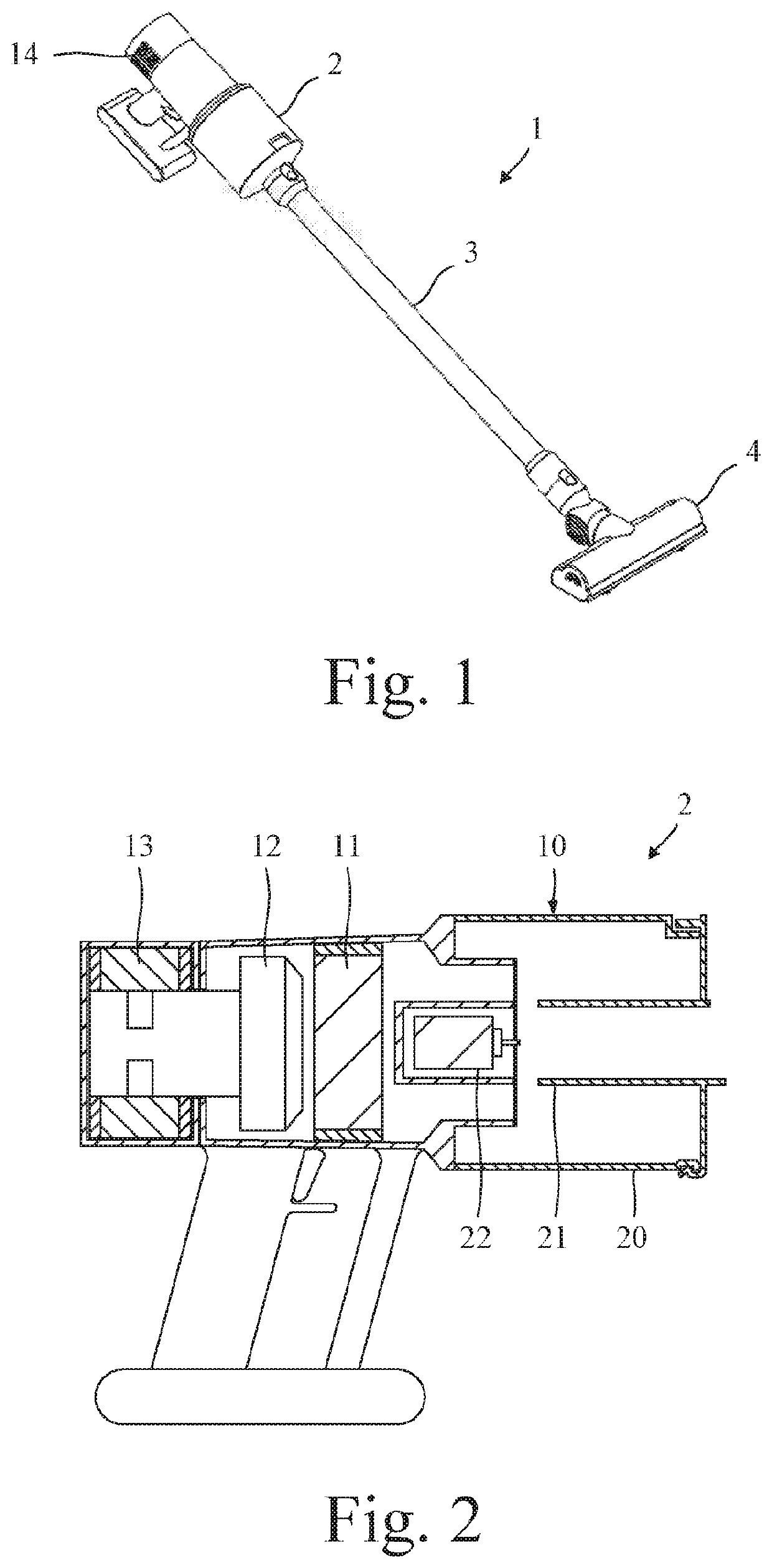
[0038]The vacuum cleaner 1 of FIG. 1 comprises a handheld unit 2 attached to a cleaner head 4 by means of an elongate tube 3. The elongate tube 3 is detachable from the handheld unit 2 such that the handheld unit 2 may be used as a standalone vacuum cleaner.

[0039]Referring now to FIGS. 2 to 7, the handheld unit 2 comprises a dirt separator 10, a pre-motor filter 11, a vacuum motor 12 and a post-motor filter 13. The pre-motor filter 11 is located downstream of the dirt separator 10 but upstream of the vacuum motor 12, and the post-motor filter 13 is located downstream of the vacuum motor 12. During use, the vacuum motor 12 causes dirt-laden fluid to be drawn in through a suction opening in the underside of the cleaner head 4. From the cleaner head 4, the dirt-laden fluid is drawn along the elongate tube 3 and into the dirt separator 10. Dirt is then separated from the fluid and retained within the dirt separator 10. The cleansed fluid exits the dirt separator 10 and is drawn through ...


PUM

PropertyMeasurementUnit
Diameteraaaaaaaaaa
Areaaaaaaaaaaa

Abstract

A dirt separator for a vacuum cleaner includes a chamber having an inlet through which dirt-laden fluid enters and an outlet through which cleansed fluid exits the chamber. A disc located at the outlet rotates about a rotational axis and comprises holes through which the cleansed fluid passes. The inlet is defined by an end of an inlet duct that extends within the chamber, and a separation distance between the centre of the inlet and the centre of the disc is no greater than the diameter of the inlet.

Description

CROSS-REFERENCE TO RELATED APPLICATIONS[0001]This application is a national stage application under 35 USC 371 of International Application No. PCT / GB2018 / 052140, filed Jul. 27, 2018, which claims the priority of United Kingdom Application No. 1712930.5, filed Aug. 11, 2017, the entire contents of each of which are incorporated herein by reference.FIELD OF THE DISCLOSURE[0002]The present invention relates to a dirt separator for a vacuum cleaner.BACKGROUND OF THE DISCLOSURE[0003]The dirt separator of a vacuum cleaner may comprise a porous bag or a cyclonic separator. However, both types of separator have their disadvantages. For example, the pores of a bag quickly clog with dirt during use, whilst the pressure consumed by a cyclonic separator can be high.SUMMARY OF THE DISCLOSURE[0004]According to various aspects, the present invention provides a dirt separator for a vacuum cleaner, the dirt separator comprising: a chamber having an inlet through which dirt-laden fluid enters the ch...

Claims


Application Information

Patent Timeline
IPC IPC(8): A47L9/16A47L9/10B01D33/00B01D33/15B04C5/185
CPCA47L9/165B04C5/185B01D33/155A47L9/102A47L9/1675B01D33/0041A47L5/24B01D45/08B01D45/14B01D33/15
Inventor PERCY-RAINE, CHARLES HOWARDISAACS, ANDREW JOHNCAMPBELL-HILL, ALEXANDER MICHAEL
Owner DYSON TECH LTD
Why Eureka
Try Eureka