

Multifunctional seat arrangement for a passenger cabin of a vehicle
- Summary
- Abstract
- Description
- Claims
- Application Information
AI Technical Summary
Benefits of technology
Problems solved by technology
Method used
Image

Examples
Embodiment Construction
[0042]The following detailed description is merely illustrative in nature and is not intended to limit the embodiments of the subject matter or the application and uses of such embodiments. As used herein, the word “exemplary” means “serving as an example, instance, or illustration.” Any implementation described herein as exemplary is not necessarily to be construed as preferred or advantageous over other implementations. Furthermore, there is no intention to be bound by any expressed or implied theory presented in the preceding technical field, background, brief summary or the following detailed description.
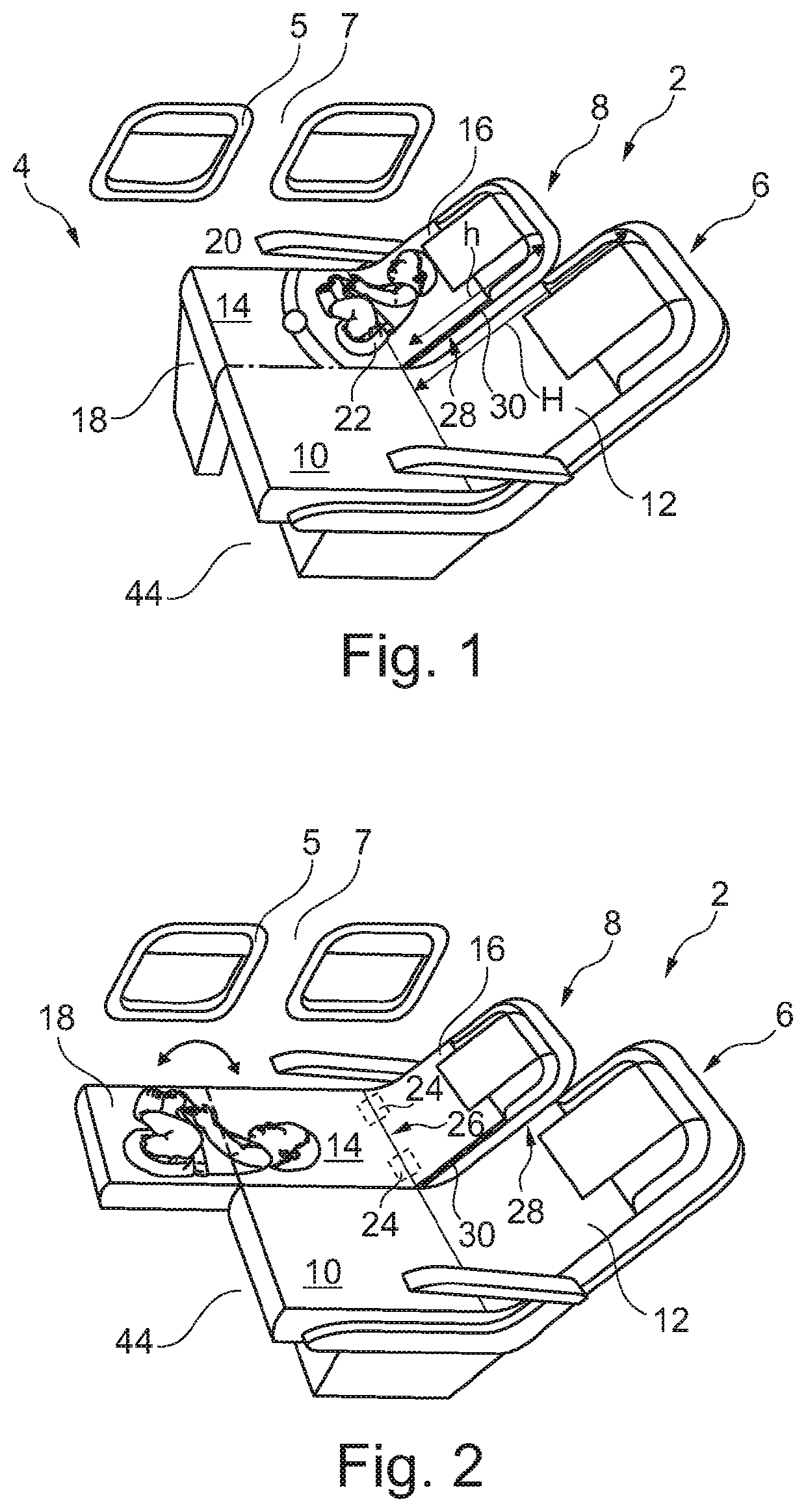
[0043]FIG. 1 shows a multifunctional seat arrangement 2 for a passenger cabin 4 of a vehicle. The seat arrangement 2 has, in the exemplary embodiment shown, a first seat 6 and a second seat 8 which is laterally arranged directly adjacent to the first seat 6. The second seat 8 directly adjoins a cabin interior trim 7 and, as a result, is oriented toward a cabin window 5.
[0044]The...
PUM
 Abstract
Description
Claims
Application Information