Embedded receiver for fasteners

a receiver and fastener technology, applied in the field of fasteners, can solve the problems of compromising the resistance to the extraction of the fastener, affecting the extraction resistance of the fastener, and tending to crush the material downwards

Inactive Publication Date: 2013-01-03
JAFFE JONATHAN E
View PDF33 Cites 4 Cited by
  • Summary
  • Abstract
  • Description
  • Claims
  • Application Information

AI Technical Summary

Benefits of technology

[0015]The present disclosure relates to fasteners for connecting objects to fabricated bodies, and more particularly presents an embedded receiver plate that provides tri-axial motion resistance for a fastener, wherein the fastener may be inserted at an imprecisely determined location within a fastener target area. One or more receiver plates may be embedded in a fabricated body for further resistance to lateral motion and extraction forces. The embedded receiver may be used with spike-type fasteners and optionally may be used with self-tapping type screws.
[0016]It is to be understood that both the foregoing general description and the following detailed description are exemplary and provided for purposes of explanation only, and are not restrictive of the subject matter claimed. Further features and objects of the present disclosure will become more fully apparent in the following description of example embodiments and from the appended claims

Problems solved by technology

This is a problem well known to anyone who has hung a very heavy picture on a simple nail that was driven into gypsum-based wallboard.
The nail will tend to crush the material downward as an excessive load is applied to the shaft, near the head of the nail.
This can result in an enlarged hole in the wallboard, significantly compromising the resistance to extraction of the fastener.
Forces acting on prior art spike-type fasteners, whether in the longitudinal direction of extraction or within a plane perpendicular thereto, can act to loosen such fasteners, rendering them less effective.

Method used


Image

  • Embedded receiver for fasteners
  • Embedded receiver for fasteners
  • Embedded receiver for fasteners

Examples


Embodiment Construction

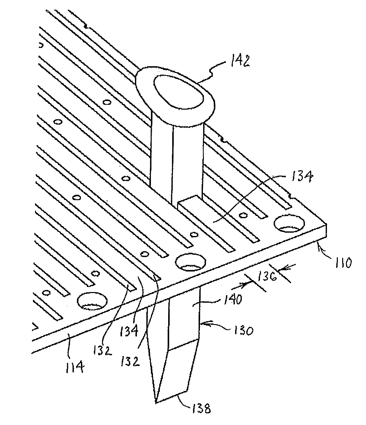
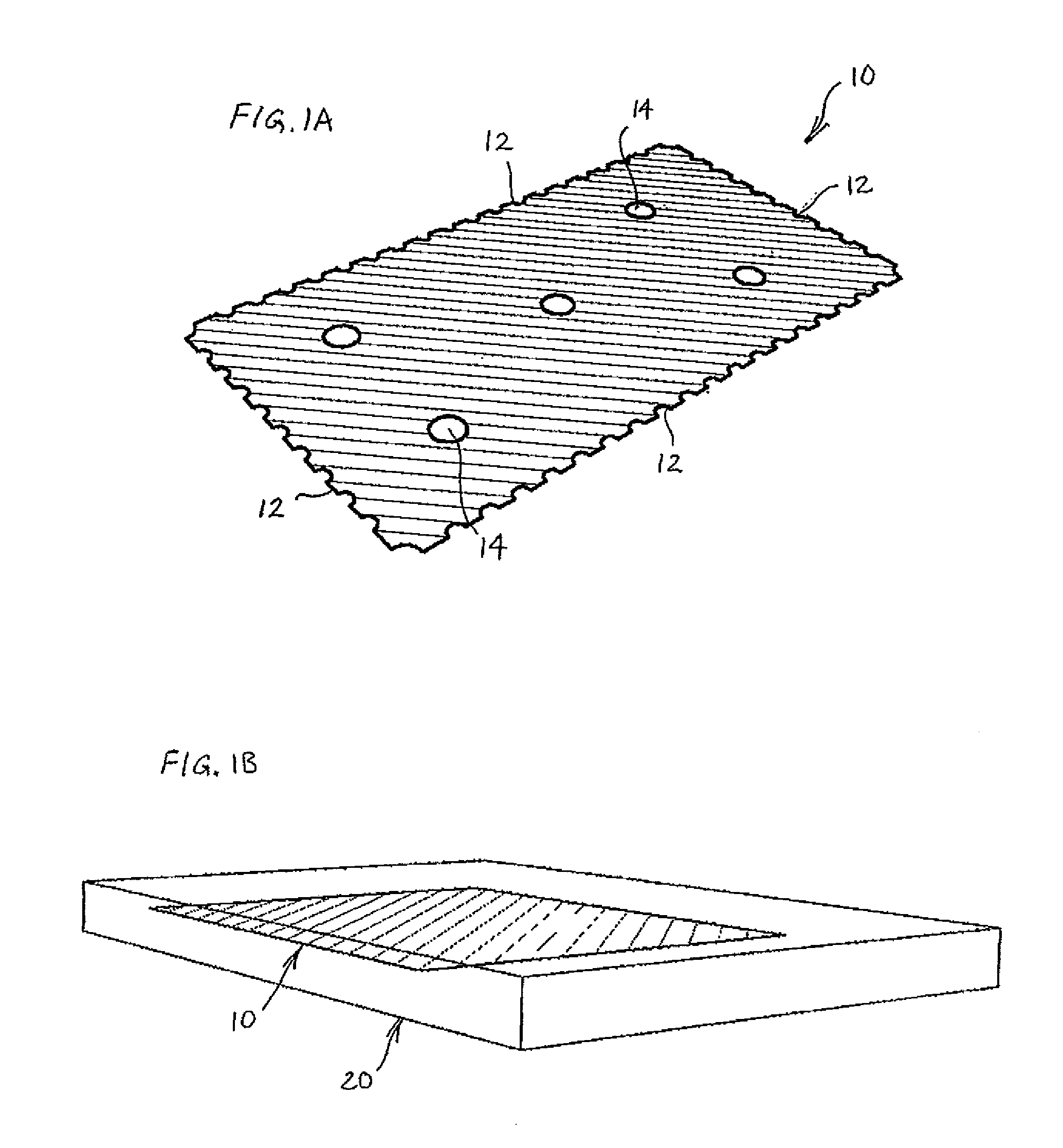
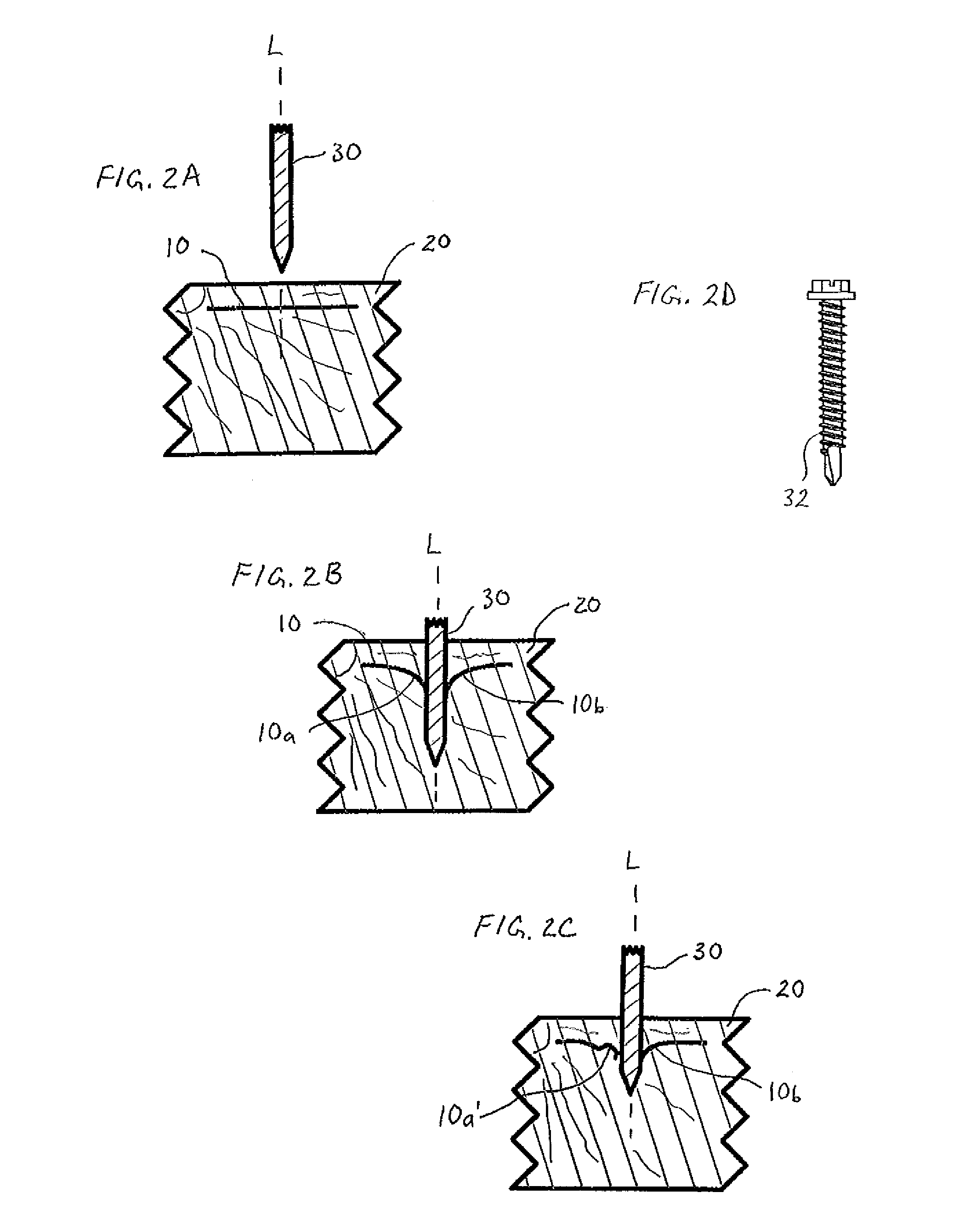
[0035]Referring generally to FIGS. 1A-9, it will be appreciated that a receiver, in the form of a plate which is to be embedded in a fabricated body into which a fastener will be inserted, may be constructed of various materials and in various configurations. Indeed, given that a receiver in the form of a plate may provide friction and resistance to extraction in the longitudinal direction of a fastener, as well as providing resistance to motion within a two dimensional plane of the receiver, which is perpendicular to the shaft of the fastener, many types of materials could be used, and the dimensions and configurations of the receiver may be determined based on desired performance characteristics.

[0036]This disclosure includes a receiver, in a form that generally will be referred to as a plate or a receiver plate, regardless of the thickness of the receiver, which in many cases will be quite thin. The receiver plate is to be embedded within a fabricated body to which something may ...


PUM

PropertyMeasurementUnit
sizesaaaaaaaaaa
motion resistanceaaaaaaaaaa
mechanical bondingaaaaaaaaaa

Abstract

A receiver plate for embedding within a fastener target area of a fabricated body is disclosed, with the receiver plate providing tri-axial motion resistance for a fastener that may be inserted into the fabricated body and through the receiver plate at an imprecisely determined location within the fastener target area. Also disclosed is a fabricated body adapted for insertion of fasteners within a target area comprising a molded body portion, and a receiver plate embedded within the molded body portion in a target area. Further disclosed is a fastener and receiver plate for use with a body in which the receiver plate is embedded, wherein the fastener has a head, a shaft and a tapered tip.

Description

CROSS-REFERENCE TO RELATED APPLICATION[0001]This application is a continuation-in-part of and claims the benefit of U.S. Provisional Patent Application No. 61 / 503,952 which was filed Jul. 1, 2011, the disclosure of which is hereby incorporated by reference in its entirety.BACKGROUND[0002]1. Field of the Invention[0003]This disclosure relates to fasteners for connecting objects to bodies, and more particularly to an embedded receiver for fasteners.[0004]2. Discussion of the Prior Art[0005]Fasteners come in many shapes and sizes. Most fasteners generally serve to connect two or more objects. Nails, which is a common name for small spikes, and other spike-type fasteners, have been around for centuries. Unlike receivers for threaded fasteners, such as wing nuts, speed nuts, T-nuts, hex nuts, etc., spike-type fasteners do not have equivalent individual receivers. Instead, the receiver function for a spike-type fastener generally is provided by the material into which the fastener is driv...

Claims


Application Information

Patent Timeline
Patent Type & Authority Applications(United States)
IPC IPC(8): B32B3/22B32B21/08B32B7/02B32B3/24B32B27/04B32B7/04
CPCF16B5/02F16B15/00F16B15/06F16B25/0031Y10T428/24132E01B3/46E01B9/06Y10T428/24273E01B3/10B32B3/266B32B21/04B32B2260/00B32B2260/026B32B2419/00E01B9/12E04C2/00E04C2/06E04C2/46F16B21/10F16B21/20F16B39/22F16B39/24Y10T428/249923Y10T428/31504Y10T428/31989Y10T428/8305
Inventor JAFFE, JONATHAN E.
Owner JAFFE JONATHAN E
Why Eureka
Try Eureka