

System and Method for Constructing Elements of Interest (EoI)-Focused Panoramas of an Oral Complex
- Summary
- Abstract
- Description
- Claims
- Application Information
AI Technical Summary
Benefits of technology
Problems solved by technology
Method used
Image

Examples
Embodiment Construction
[0029]Specific embodiments of the invention will now be described in detail with reference to the accompanying FIGS. 1A-7. In the following detailed description of embodiments of the invention, numerous specific details are set forth in order to provide a more thorough understanding of the invention. In other instances, well-known features have not been described in detail to avoid obscuring the invention. Embodiments disclosed include an automated parsing pipeline system and method for anatomical localization and condition classification.
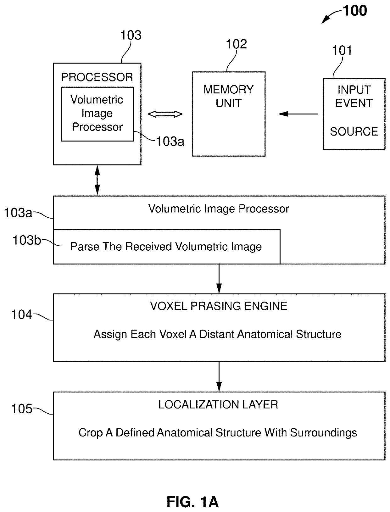
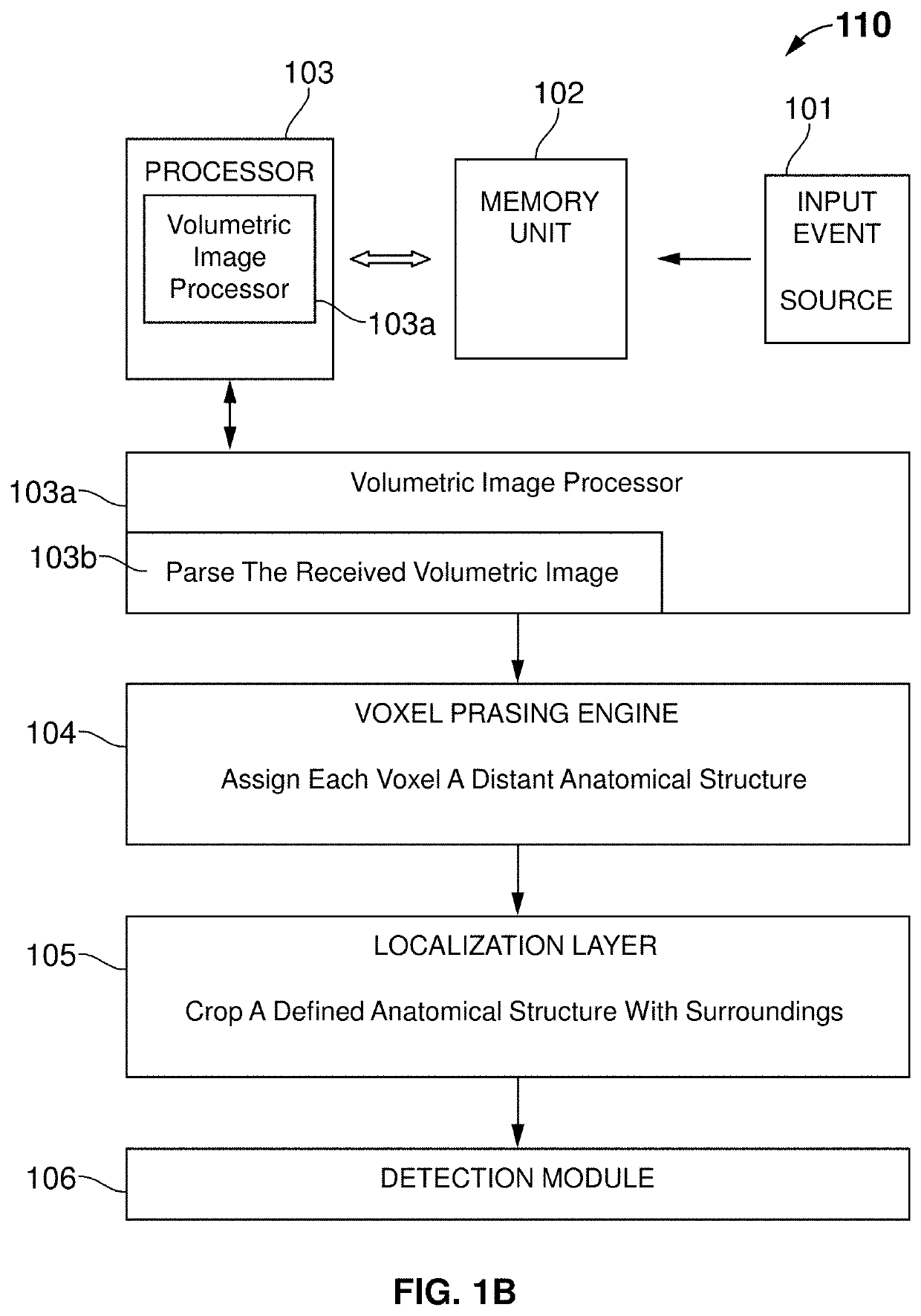
[0030]FIG. 1A illustrates a block diagram 100 of the system comprising an input event source 101, a memory unit 102 in communication with the input event source 101, a processor 103 in communication with the memory unit 102, a volumetric image processor 103a in communication with the processor 103, a voxel parsing engine 104 in communication with the volumetric image processor 103a and a localizing layer 105 in communication with the voxel parsing ...
PUM
 Abstract
Description
Claims
Application Information