Method and system for generating a display comprising a curve representative of a circular limit on a terrestrial surface

a technology of circular limit and display screen, applied in the field of method and system, can solve the problems of approximation currently used, errors of about several hundred nautical miles, and the insufficient computational and/or display resources of most navigation display, and achieve the effect of reducing these drawbacks

Inactive Publication Date: 2020-06-04
AIRBUS OPERATIONS (SAS)
View PDF0 Cites 0 Cited by
  • Summary
  • Abstract
  • Description
  • Claims
  • Application Information

AI Technical Summary

Benefits of technology

[0007]An aim of the present invention is to mitigate these drawbacks by providing a method and system for generating

Problems solved by technology

However, most navigation displays do not possess sufficient computational and/or display resources to represent an ellipse or an elliptical arc.
Speci

Method used


Image

  • Method and system for generating a display comprising a curve representative of a circular limit on a terrestrial surface
  • Method and system for generating a display comprising a curve representative of a circular limit on a terrestrial surface
  • Method and system for generating a display comprising a curve representative of a circular limit on a terrestrial surface

Examples


first embodiment

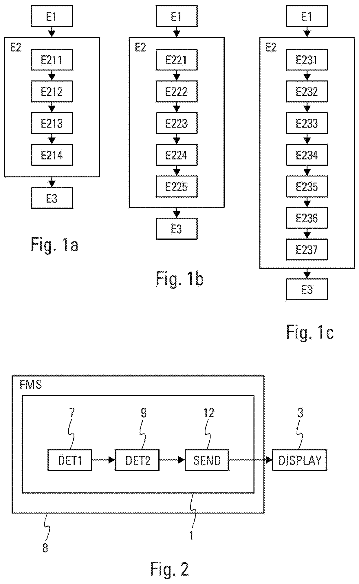
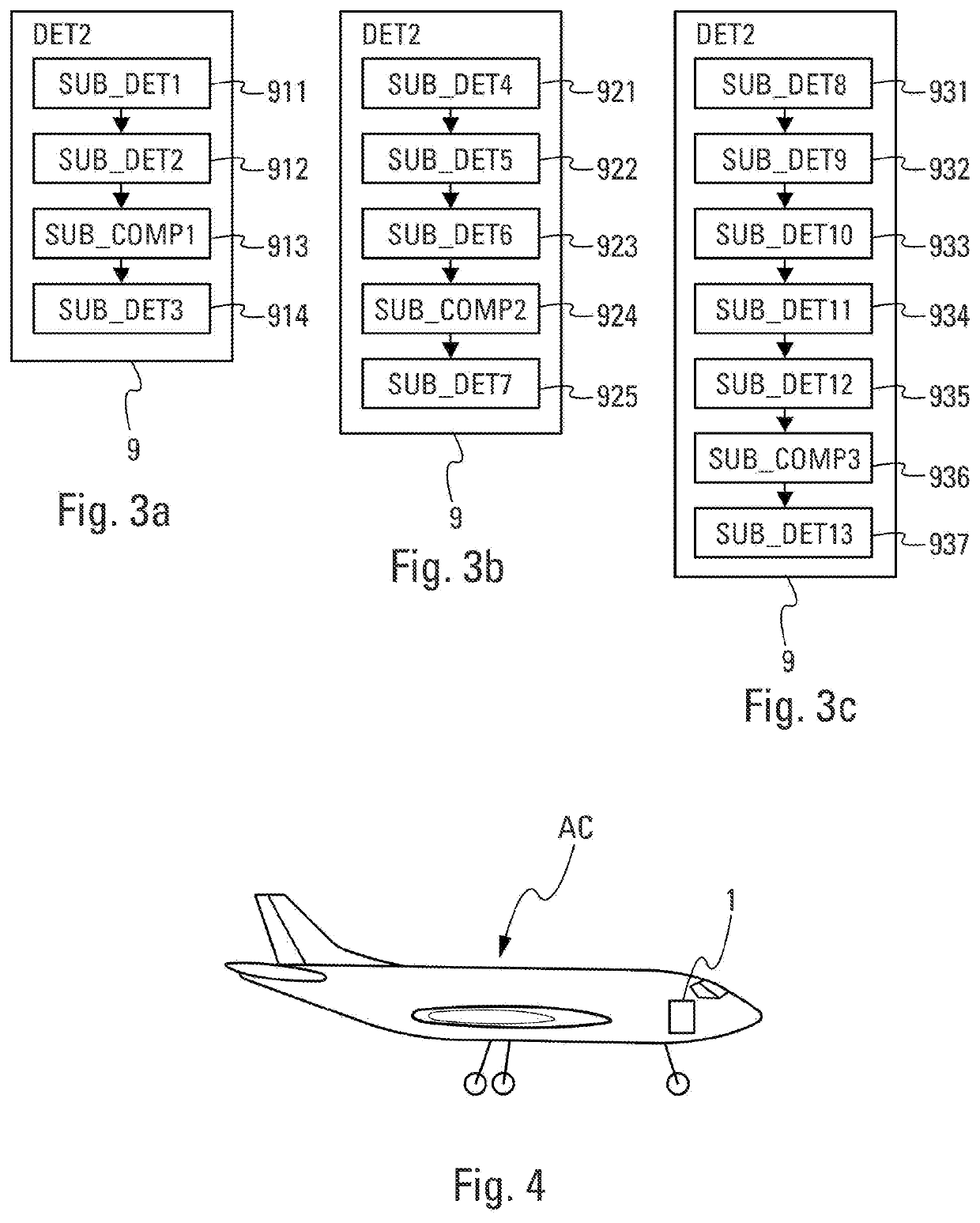
[0084]In this first embodiment, the determination module 9 furthermore comprises:[0085]a determination submodule SUB_DET2912 configured to determine the center C2 corresponding to an orthogonal projection onto the display plane 11 of the center C1,[0086]a computation submodule SUB_COMP1913 configured to compute a radial distance on the display plane 11 between the curve point P and the center C2 and[0087]a determination submodule SUB_DET3914 configured to determine the curve comprising the points of the circle 10 the center of which corresponds to the center C2 and the radius R2 of which corresponds to the radial distance.

[0088]According to a second embodiment (FIG. 3b), the determination module 9 comprises a determination submodule SUB_DET4921 configured to determine at least two auxiliary curve points. Each of the auxiliary curve points respectively corresponds to an orthogonal projection onto the display plane 11 of a point of the circle 5.

[0089]According to a first variant, the ...

second embodiment

[0092]In this second embodiment, the determination module 9 furthermore comprises:[0093]a determination submodule SUB_DET6923 configured to determine the center C2 corresponding to an orthogonal projection onto the display plane 11 of the center C1,[0094]a computation submodule SUB_COMP2924 configured to compute a radial distance on the display plane 11 between the curve point P and the second center C2 and[0095]a determination submodule SUB_DET7925 configured to determine the curve comprising the points of the circle 10 the center of which corresponds to the center C2 and the radius R2 of which corresponds to the radial distance.

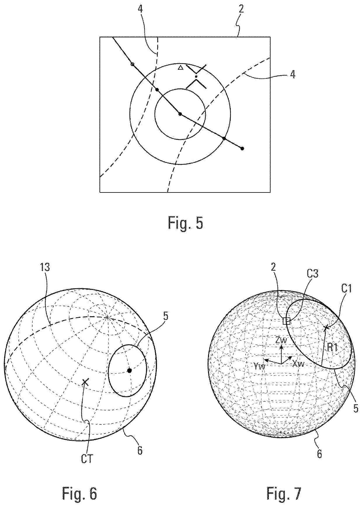
[0096]In a third embodiment (FIG. 3c), the terrestrial surface 6 is considered to be a spherical surface having a center called the center of the Earth CT and a radius called the radius of the Earth RT.

third embodiment

[0097]In this third embodiment, the determination module comprises:[0098]a determination submodule SUB_DET8931 configured to determine coordinates of the center C3 of the display zone 2[0099]a determination submodule SUB_DET9932 configured to determine a vector normal to an auxiliary plane, the auxiliary plane containing the center of the Earth CT, the center C1 of the circle 5 and the center C3 of the display zone 2,[0100]a determination submodule SUB_DET10933 configured to determine a cone angle having an apex at the center of the Earth CT and a base corresponding to the circle 5,[0101]a determination submodule SUB_DET11934 configured to determine the curve point P, the curve point P being determined by rotating the center C1, about the normal vector determined by the determination submodule 932, in a direction pointing toward the center C3 of the display zone 2, i.e., the center determined by the determination submodule 931,[0102]a determination submodule SUB_DET12935 configured ...


PUM


Abstract

A generating system comprises a module for determining coordinates of a first center and a first radius of a first circle, a module for determining a curve comprising points of a second circle having a second radius and a second center corresponding to an orthogonal projection of the first center onto a display plane and a sending module configured to send to a display module a signal representative of the curve to be displayed. The second radius corresponds to a distance between the second center and a curve point. The curve point corresponds to an orthogonal projection onto the display plane of a point of the first circle. The generating system displays on the display module a curve representative of a small circle with a sufficient precision without requiring substantial computational or display resources.

Description

CROSS-REFERENCES TO RELATED APPLICATIONS[0001]This application claims the benefit of the French patent application No. 1872111 filed on Nov. 30, 2018, the entire disclosures of which are incorporated herein by way of reference.FIELD OF THE INVENTION[0002]The present invention relates to a method and system for generating a display using a display module comprising at least one curve representative of at least one arc of a circle. The circle, generally called a “small circle,” corresponds to a circular limit on a terrestrial surface.BACKGROUND OF THE INVENTION[0003]The navigation display of an aircraft displays data collected by navigation instruments. Generally, the navigation display must represent map data of a terrestrial surface on a planar surface that is tangent to the terrestrial surface at the center of the planar surface.[0004]The map data required for navigation include circles or arcs centered on a point of the terrestrial surface and having a defined radius. These circle...

Claims


Application Information

Patent Timeline
IPC IPC(8): G06T11/20G01C21/00B64D43/00
CPCB64D43/00G01C21/005G06T11/203
Inventor RAYNAUD, SYLVAINQUIROZ-HERNANDEZ, ESTEBAN
Owner AIRBUS OPERATIONS (SAS)
Why Eureka
Try Eureka