
Method for transmitting and receiving signal by means of beam in wireless communication system, and apparatus for said method

a wireless communication system and beam technology, applied in the field of wireless communication systems, can solve the problems of needing more advanced mobile communication systems, and achieve the effects of reducing the payload size of beam-related information, reducing the overhead of reporting, and reducing the complexity of measurement of a u

Active Publication Date: 2020-06-18
LG ELECTRONICS INC
View PDF0 Cites 21 Cited by
  • Summary
  • Abstract
  • Description
  • Claims
  • Application Information

AI Technical Summary

Benefits of technology

The present patent aims to reduce reporting overhead and measurement complexity of a user equipment (UE) by reducing the payload size of beam-related information when the UE reports beam-related information. This also helps in load balancing in a multi-cell environment by performing beam measurement for a specific direction of a cell configured by a base station.

Problems solved by technology

However, as current mobile communication systems suffer resource shortages and users demand even higher-speed services, development of more advanced mobile communication systems is needed.

Method used


Image

  • Method for transmitting and receiving signal by means of beam in wireless communication system, and apparatus for said method
  • Method for transmitting and receiving signal by means of beam in wireless communication system, and apparatus for said method
  • Method for transmitting and receiving signal by means of beam in wireless communication system, and apparatus for said method

Examples


first embodiment

ng Reporting Overhead by Restricting Cell and / or SS Block to be Used for Beam Management

[0320]In the NR system, as described above, a method of performing beam management using an SS block and / or MRS for initial access and radio resource measurement (RRM) may be considered. In this case, the SS block includes a PSS, an SSS, and a PBCH, and may denote at least one of a PSS, an SSS, and a PBCH. Furthermore, for convenience of description, the method proposed in this specification is described based on a method using an SS block, but may also be identically applied to a method using an MRS.

[0321]In this case, for beam management, an L1 / L2 report for SS block measurement may be considered. Beam direction information and / or RSRP (e.g., L1-RSRP) may be considered as reporting information. In this case, if a multi-cell / transmit point (TP) is considered, a method using a cell ID indicator and the SS block indicator of a corresponding cell ID as the beam direction information may be consider...

second embodiment

g Reporting Overhead in Relation to Beam Group Reporting

[0347]Furthermore, in the NR system, as described above, multiple beam reportings for reporting in a beam group unit may be considered. In this case, a UE needs to report a beam group index(s), a beam index (e.g., Tx beam index) and / or a measurement quantity corresponding to each beam index. Accordingly, a payload size for the reporting may be set to be very large.

[0348]In this case, the beam index may be represented as a CSI-RS resource ID, the port index of a corresponding CSI-RS resource ID, an SS block index and / or a DMRS port index. Furthermore, the measurement quantities may be represented as reference signal received power (RSRP), reference signal received quality (RSRQ) and / or a channel quality indicator (CQI) (for a CSI-RS). Hereinafter, in this specification, a case where a reported measurement quantity is RSRP is assumed, for convenience of description.

[0349]As described in the beam group reporting part, in the NR sy...


PUM


Abstract

The present specification provides a method for transmitting and receiving a signal by means of a beam in a wireless communication system. Specifically, a method for a terminal for reporting beam-related information in a wireless communication system may comprise the steps of: receiving one or more particular signals for beam management from a base station; and reporting, to the base station, beam information for one or more beams on the basis of result of measurements by means of the one or more particular signals.

Description

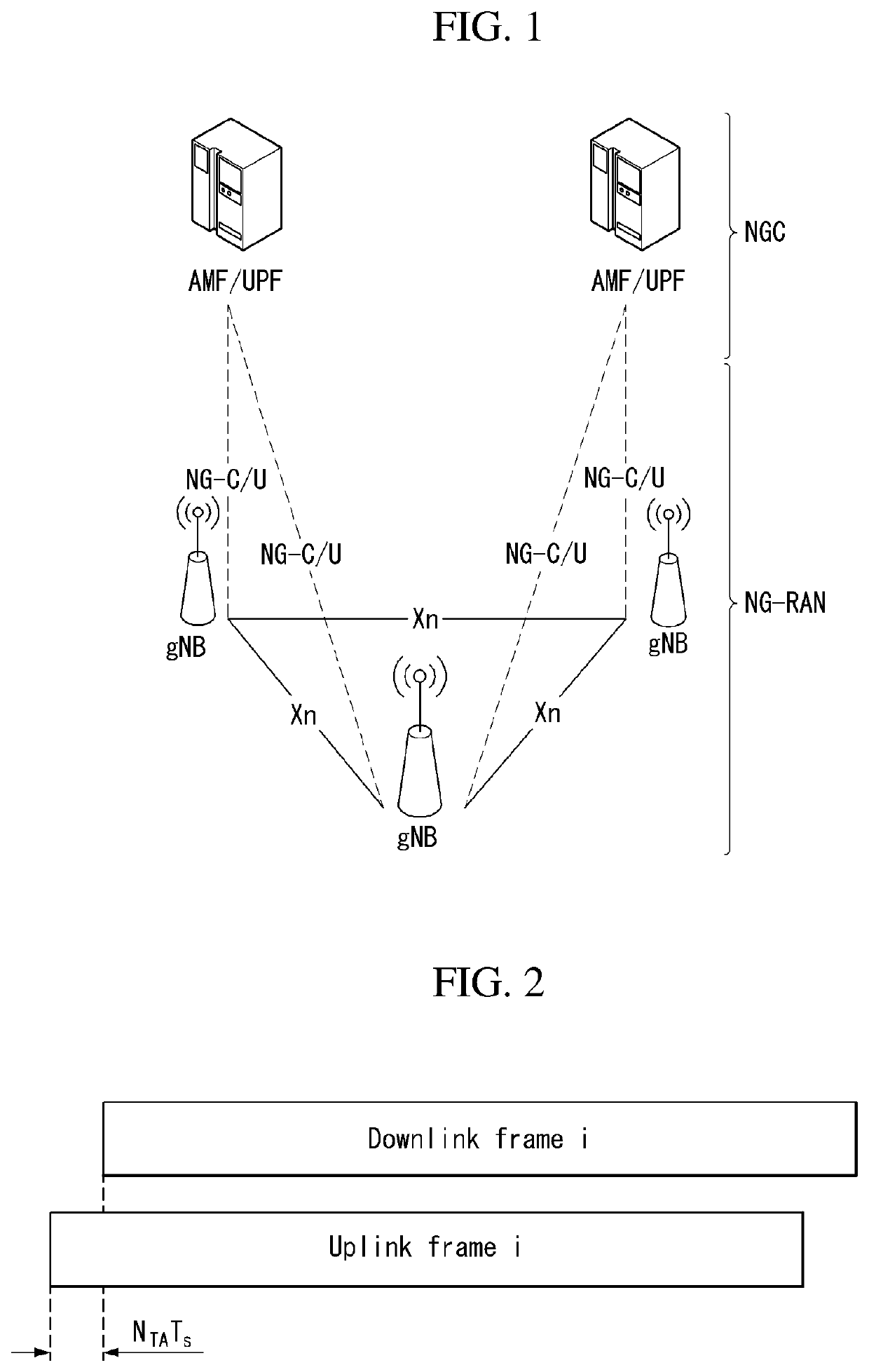
TECHNICAL FIELD[0001]The present disclosure relates to a wireless communication system and, more particularly, to a method for transmitting and receiving signals using a beam and an apparatus supporting the same.BACKGROUND ART[0002]Mobile communication systems have been developed to provide voice services while guaranteeing user mobility. Such mobile communication systems have gradually expanded their coverage from voice services through data services up to high-speed data services. However, as current mobile communication systems suffer resource shortages and users demand even higher-speed services, development of more advanced mobile communication systems is needed.[0003]The requirements of the next-generation mobile communication system may include supporting huge data traffic, a remarkable increase in the transfer rate of each user, the accommodation of a significantly increased number of connection devices, very low end-to-end latency, and high energy efficiency. To this end, v...

Claims


Application Information

Patent Timeline
Patent Type & Authority Applications(United States)
IPC IPC(8): H04W16/28H04W24/10H04W76/11H04W56/00H04L5/00H04W80/08H04B17/318
CPCH04W16/28H04W76/11H04W24/10H04L5/0051H04W80/08H04W56/001H04B17/318H04L5/0023H04L5/0048H04B7/06H04W56/00H04B17/24H04B17/327
Inventor AHN, MINKIKANG, JIWONPARK, JONGHYUNKIM, KIJUNPARK, HAEWOOKYOON, SUKHYON
Owner LG ELECTRONICS INC
Learn More