
Eureka
For R&D, Eureka makes reading and utilizing patents & technical documents easy.
Eureka AIR
Designed for self-driven R&D workflows. Generate viable solutions, solve complex R&D challenges, empower your innovation with AI.

Eureka Materials
Designed for material experts only. Revolutionize your material R&D, from search, analyze, to developing new materials.

TechResearch
Generate reliable direction feasibility study reports for your R&D in just a few steps.

TechSeek
Discover and master advanced knowledge NOW. Basics, ideas, possibilities, all at once.

TechMind
As an expert in R&D Theories, TechMind can generates customized viable solutions instantly.

TechRisk
Analyze your overall solution with one click, know your potential R&D risks in advance.

TechMonitor
Get weekly tech updates, stay abreast of the latest tech innovations and key insights.
Composite tread with targeted stiffness gradient and method of making
- Summary
- Abstract
- Description
- Claims
- Application Information
AI Technical Summary
Benefits of technology
Problems solved by technology
Method used
Image

Examples
second embodiment
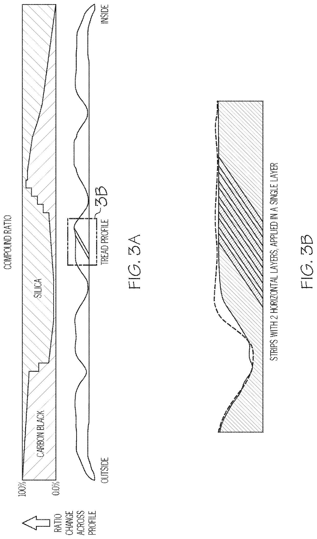
[0032]FIGS. 3A, 3B, and FIGS. 4A and 4B illustrates a green tire tread 400 that is formed from a single layer of coextruded strips. The first compound (shown in red) is selected to be a high silica tread compound, while the second compound represented (shown in yellow), is selected to have a desired property, in this case stiffness, but could also be other properties such as wet grip. As shown, the coextruded strips have different tread compound ratios that vary axially across the tread profile. The outer lateral edge 420 is formed of a coextruded strip having a range of 90-100% of the first (shown in black) compound. The ribs or tread blocks 430 and 440 are formed in the range of 70-90% of the second (yellow) compound, and 10-30% of the first (black compound). The tread has a transition section 435 located between the outer lateral edge 420 and the rib 440. In the transition section 435, the second compound (yellow) gradually increases. Rib or tread block 410 is primarily 90-100% o...
first embodiment
[0034]The stiffness may be characterized by the dynamic modulus G′, which are sometimes referred to as the “shear storage modulus” or “dynamic modulus,” reference may be made to Science and Technology of Rubber, second edition, 1994, Academic Press, San Diego, Calif., edited by James E. Mark et al, pages 249-254. The shear storage modulus (G′) values are indicative of rubber compound stiffness which can relate to tire performance. In a first embodiment, the second rubber compound comprises a stiff rubber composition having a shear storage modulus G′ measured at 1% strain and 100° C. according to ASTM D5289 ranging from 15 to 50 MPa. In a more preferred embodiment, the second rubber compound comprises a rubber composition having a shear storage modulus G′ measured at 1% strain and 100° C. according to ASTM D5289 ranging from 25 to 40 MPa. In the most preferred embodiment, the second rubber compound comprises a rubber composition having a shear storage modulus G′ measured at 1% strain...
PUM
| Property | Measurement | Unit |
|---|---|---|
| Temperature | aaaaa | aaaaa |
| Fraction | aaaaa | aaaaa |
| Fraction | aaaaa | aaaaa |
Abstract
Description
Claims
Application Information
 - R&D Engineer
- R&D Manager
- IP Professional
- Industry Leading Data Capabilities
- Powerful AI technology
- Patent DNA Extraction
Browse by: Latest US Patents, China's latest patents, Technical Efficacy Thesaurus, Application Domain, Technology Topic, Popular Technical Reports.
© 2024 PatSnap. All rights reserved.Legal|Privacy policy|Modern Slavery Act Transparency Statement|Sitemap|About US| Contact US: help@patsnap.com