Wire harness

a wire harness and wire technology, applied in the direction of insulated conductors, cables, electric/fluid circuits, etc., can solve the problems of difficulty in transporting the wire harness to the vehicle assembly site, and the portion that can be bent when the vehicle is routed is not necessarily positioned at a position, so as to reduce the cost of transportation

Active Publication Date: 2020-06-25
YAZAKI CORP
View PDF0 Cites 2 Cited by
  • Summary
  • Abstract
  • Description
  • Claims
  • Application Information

AI Technical Summary

Benefits of technology

[0015]According to the aspect (5), since the flexible pipe portion is formed in the middle of the exterior member and the packing bent portion is formed using the flexible pipe portion, the wire harness can be packed in the compact state by the packing bent portion. In addition, according to the present invention, the routing path regulating portion is provided at the packing bent portion by assembling the length adjustment member formed with the pipe attaching member for the desired path, so that the wire harness can be regulated in the desired path when routing the harness even if there is the packing bent portion.
[0016]According to one or more embodiments, it is possible to provide a wire harness that can be bent when packing the harness and can regulate the path when the vehicle is routed. In addition, according to the present embodiment, there is also an effect that the wire harness can be packed in the compact state. Accordingly, there is an effect that the more wire harnesses can be accommodated in the box and transported than before. In addition, since the large number of wire harnesses can be transported at a time, there is an effect that transportation cost can be reduced, for example.

Problems solved by technology

In a related art, since a wire harness is long, it is very difficult to transport the wire harness to a vehicle assembly site as it is after manufacturing.
However, the portion that can be bent when the vehicle is routed is not necessarily positioned at a position suitable for the bent portion (folded portion) at the time of packing.

Method used


Image

  • Wire harness
  • Wire harness
  • Wire harness

Examples


first embodiment

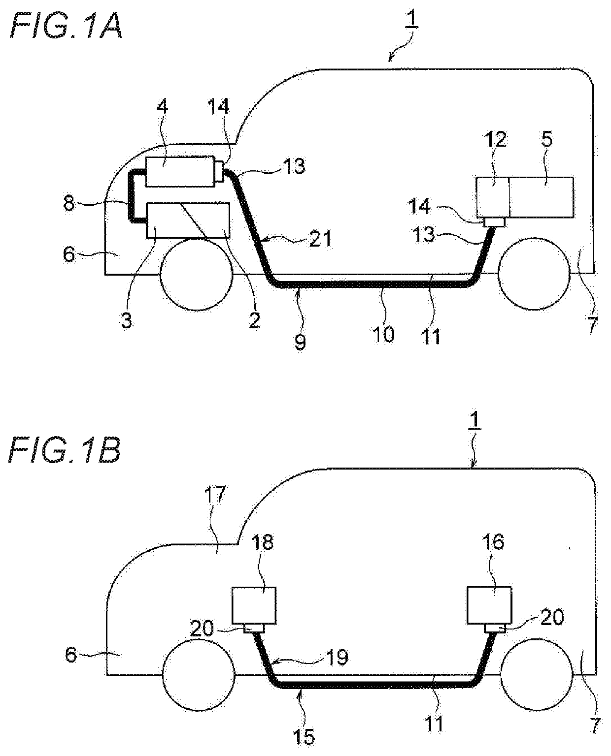
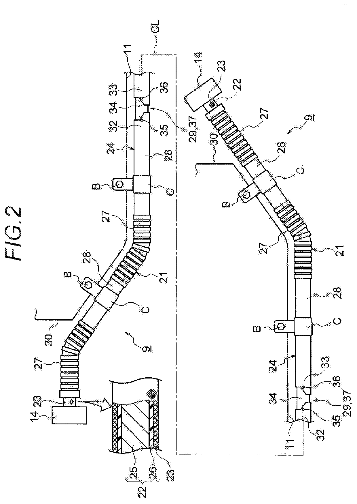
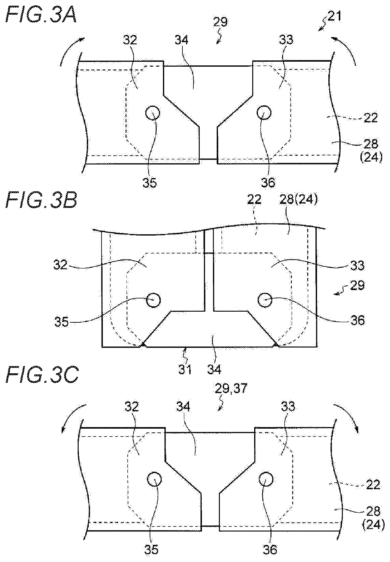
[0029]A first embodiment will be described below with reference to the drawings. FIGS. 1A and 1B are views showing a wire harness according to an embodiment. FIG. 1A is a schematic view showing a routing state of a high voltage wire harness. FIG. 1B is a schematic view showing a routing state of a low voltage wire harness different from FIG. 1A. In addition, FIG. 2 is a schematic view showing a configuration of the wire harness. FIGS. 3A to 3C are schematic views showing a joint mechanism of FIG. 2. FIG. 3A is a schematic view showing a state when manufacturing the harness. FIG. 3B is a schematic view showing a state when packing the harness. FIG. 3C is a schematic view showing a state when routing the harness.

[0030]In the present embodiment, the present invention is applied to a wire harness routed in a hybrid automobile. Incidentally, the present invention is not limited to the hybrid automobile, and may be applied to an automobile such as a PHV or an electric vehicle using a moto...

second embodiment

[0068]A second embodiment will be described below with reference to the drawings. FIG. 4 is a schematic view showing a configuration of another wire harness. In addition, FIGS. 4 to 6B are views relating to the manufacturing to routing of the wire harness. Incidentally, the same components as in the first embodiment are denoted by the same reference numerals, and a detailed description thereof is omitted.

[0069]9 and Harness Main Body 21 of Second Embodiment>

[0070]In FIG. 4, the long wire harness 9 routed through the vehicle floor 11 includes the harness main body 21 and the shield connectors 14 respectively disposed at the both terminals of the harness main body 21. In addition, the wire harness 9 includes the clamp C for routing itself at the predetermined position, and the water stop member (for example, the grommet or the like) (not shown). The harness main body 21 includes the two long conductive paths 22, the shield member 23 that collectively covers the conductive paths 22, an...

third embodiment

[0083]A third embodiment will be described below with reference to the drawings. FIG. 7 is a schematic view showing a configuration of still another wire harness. In addition, FIGS. 8A to 9B are views relating to the manufacture to routing of the wire harness. Incidentally, the same components as in the first embodiment are denoted by the same reference numerals, and a detailed description thereof is omitted.

[0084]9 and Harness Main Body 21 of Third Embodiment>

[0085]In FIG. 7, the long wire harness 9 routed through the vehicle floor 11 includes the harness main body 21 and the shield connector 14 respectively disposed at the both terminals of the harness main body21. In addition, the wire harness 9 includes the clamp C for routing itself at the predetermined position, and the water stop member (for example, the grommet or the like) (not shown). The harness main body 21 includes the two long conductive paths 22, the shield member 23 that collectively covers the conductive paths 22, a...


PUM

PropertyMeasurementUnit
conductiveaaaaaaaaaa
shapeaaaaaaaaaa
flexibleaaaaaaaaaa

Abstract

A wire harness includes a harness main body including one or a plurality of conductive paths and an exterior member through which the one or a plurality of conductive paths is inserted, a packing bent portion arranged in a middle of the harness main body and used as a bent portion at a position suitable for packing the wire harness, and a routing path regulating portion arranged at the position suitable for packing the wire harness and configured to regulate the wire harness at a desired path when routing the wire harness.

Description

CROSS REFERENCE TO RELATED APPLICATIONS[0001]This application claims priority from Japanese Patent Application No. 2018-240582 filed on Dec. 25, 2018, the entire contents of which are incorporated herein by reference.BACKGROUND OF THE INVENTIONField of the Invention[0002]The present invention relates to a wire harness including a conductive path and an exterior member.Description of Related Art[0003]For example, a wire harness routed in an electric automobile or a hybrid automobile is long and includes one or a plurality of conductive paths and an exterior member having a pipe shape through which the conductive path is inserted. The wire harness is manufactured at a harness manufacturing site and then packed and transported to a vehicle assembly site. At the vehicle assembly site, the wire harness in a packed state is taken out from a box, and the taken out wire harness is routed to a predetermined position of the vehicle (see Patent Literature 1 below).[Patent Literature 1] JP-A-20...

Claims


Application Information

Patent Timeline
Patent Type & Authority Applications(United States)
IPC IPC(8): B60R16/02H01B7/00
CPCB60R16/0215H01B7/0045B60R16/0207H02G3/32H02G3/0468H02G3/06H02G3/0481
Inventor ADACHI, HIDEOMIOGUE, TAKESHITSURU, MASAHIDEYOSHIDA, HIROYUKINAGASHIMA, TOSHIHIROYAMADA, TETSUOYANAZAWA, KENTA
Owner YAZAKI CORP
Why Eureka
Try Eureka