Aircraft landing gear and pitch trimmer assembly

Active Publication Date: 2020-06-25
MESSIER DOWTY
View PDF0 Cites 1 Cited by
  • Summary
  • Abstract
  • Description
  • Claims
  • Application Information

AI Technical Summary

Benefits of technology

The patent text describes a way to make a simpler and more reliable actuator for a pitch trimmer. This is done by using a biasing force that keeps the actuator in a neutral position, regardless of its starting position. This allows for the use of a smaller actuator and reduces the need for a separate pressure accumulator. The actuator is also integrally formed with an oleo-pneumatic shock absorber, which makes the system even more robust.

Problems solved by technology

This reduces the likelihood of fluid loss from the actuator.

Method used


Image

  • Aircraft landing gear and pitch trimmer assembly
  • Aircraft landing gear and pitch trimmer assembly
  • Aircraft landing gear and pitch trimmer assembly

Examples


Embodiment Construction

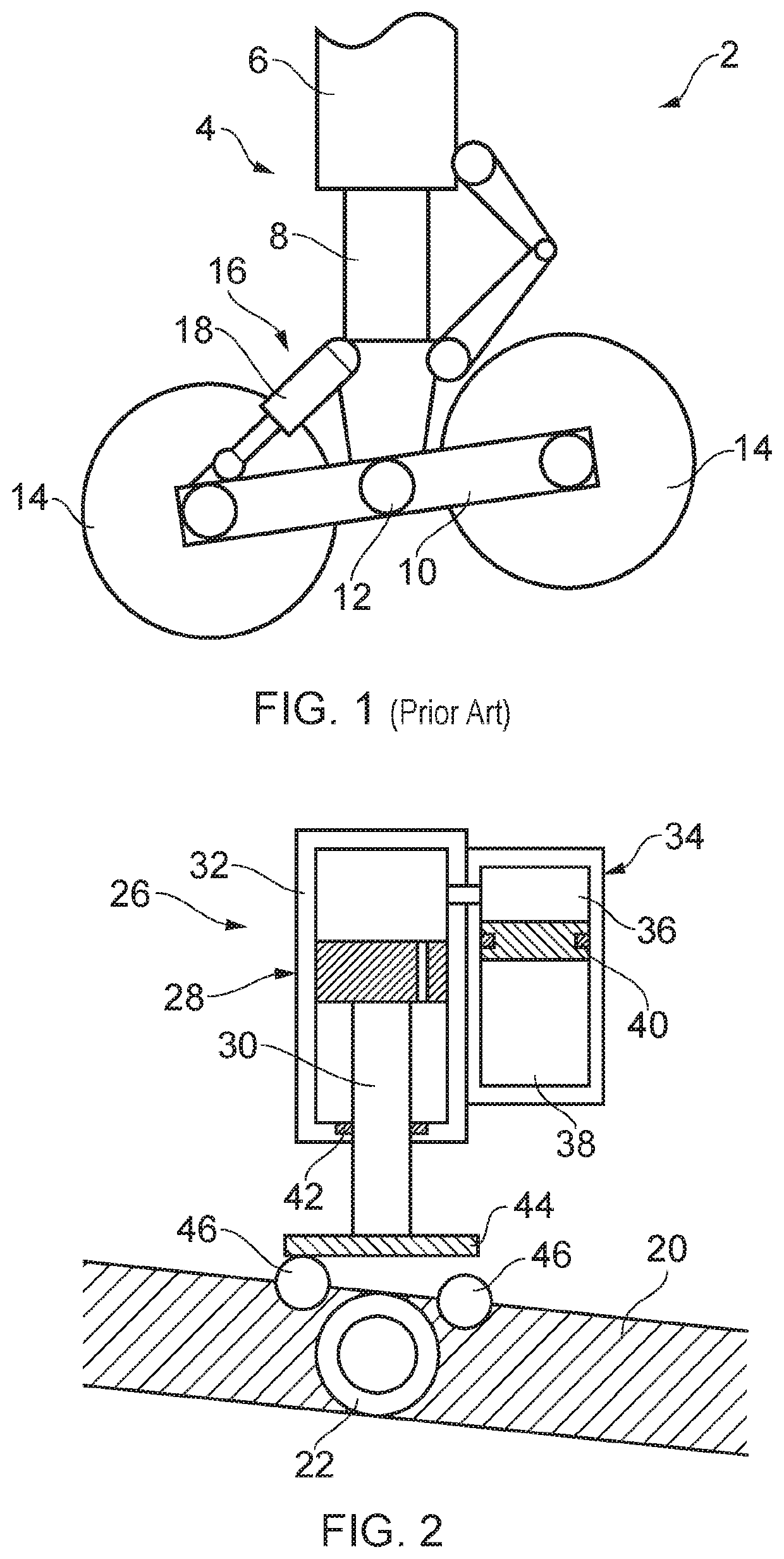
[0025]FIG. 1 schematically illustrates a typical arrangement of an aircraft main landing gear including a pitch trimmer assembly that will be readily recognised by the skilled person. The landing gear assembly 2 includes a support member 4 that has an upper portion 6 arranged to be pivotally coupled to the main body of the aircraft (not illustrated) and a lower portion 8 that is slidably received within the upper portion 6. The support member 4 typically, but not necessarily, comprises a telescopic oleo-pneumatic shock strut. The lower portion 8 of the support member is pivotally coupled to a bogie beam 10 by means of a bogie beam pivot pin 12. In the particular example illustrated in FIG. 1, the bogie beam 10 has first and second axles rotatably mounted at either end on which respective pairs of wheels 14 are mounted. In FIG. 1 only a single one of each pair of wheels 14 is illustrated for the sake of clarity. A pitch trimmer assembly 16 is coupled between the lower portion 8 of th...


PUM


Abstract

An aircraft landing gear assembly having a bogie beam pivotally coupled to a support member, and a pitch trimmer assembly including a pitch trimmer actuator configured to exert a biasing force in a first direction and a bias force transmission assembly configured to receive the biasing force in the first direction and bias the bogie beam towards a predetermined neutral position relative to the support member irrespective of the initial position of the bogie beam.

Description

[0001]This application claims the benefit of European Application No. EP 18214631.6, filed on Dec. 20, 2018, which is incorporated herein by reference.BACKGROUND OF THE INVENTION[0002]The main landing gear of larger aircraft often have multiple axles on a bogie beam (or axle truck), with the bogie beam being pivotally coupled at an approximate mid-point to a support member of the landing gear assembly, typically an oleo-pneumatic shock strut. Such landing gear assemblies also often include a pitch trimmer assembly that is generally in the form of a telescopic actuator coupled between the bogie beam and a lower portion of the shock strut. The pitch trimmer assembly has a number of possible functions including controlling the position of the bogie beam relative to the shock strut during landing and take-off phases, where for example it is often desirable for the forward portion of the bogie beam, and hence forward axle and wheel set, to be angled upwards, i.e. angled towards the under...

Claims


Application Information

Patent Timeline
IPC IPC(8): B64C25/34B64C25/40
CPCB64C25/34B64C25/40B64C25/36B64C25/60
Inventor BENNETT, IAN ROBERTSIMMONNEAUX, YANN
Owner MESSIER DOWTY
Why Eureka
Try Eureka