Aerosol product

a technology of aerosol and product, applied in the field of aerosol products, can solve the problems of inability to achieve optimal mist configuration, limited type and amount of liquefied gas, etc., and achieve the effect of simple structure and reducing limitations on applicable liquids

Inactive Publication Date: 2020-06-25
TOYO AEROSOL IND CO LTD
View PDF0 Cites 2 Cited by
  • Summary
  • Abstract
  • Description
  • Claims
  • Application Information

AI Technical Summary

Benefits of technology

[0018]The aerosol product according to claim 1 has the aerosol container including a plurality of holding spaces by being partitioned and a plurality of valves corresponding to the holding spaces, at least one of the plurality of holding spaces being a liquefied gas containing section that holds a liquefied gas, and at least one of the plurality of valves being a gas phase valve that ejects vaporized gas from the liquefied gas containing section. As the content such as a liquid and the vaporized gas mix with each other inside the nozzle, the content can be atomized into a mist of fine particles that hardly gives the sensation of coldness.
[0019]Since the content such as a liquid and the vaporized gas are ejected from respective valves, the two valves can be designed optimally as required, which reduces limitations on applicable liquids.
[0020]Also, aerosol containers having a known dual valve configuration can be utilized, which results in a simple structure.
[0021]According to the configuration set forth in claim 2, the aerosol container includes a can-like vessel and one or more content holding bags accommodated inside the can-like vessel, the liquefied gas containing section being formed by a space outside the content holding bag inside the can-like vessel, and a valve or valves other than the gas phase valve being configured to eject a content inside the content holding bag. As the content is forced out by the pressure from the liquefied gas containing section, contents that should not be mixed with a liquefied gas in storage can be accommodated, and thus the limitations on applicable liquids are further reduced.
[0022]Also, since the aerosol container is formed by one can-like vessel, the container can be designed to have a shape easy to hold for the user.
[0023]According to the configuration set forth in claim 3, the nozzle includes a fitting part that fits with stems of the plurality of valves, a mixing part where fluids ejected from the plurality of valves are mixed, and an outlet orifice for forcing out the mixed fluids. Spraying of an optimal mist is made possible by a suitable internal design of a single nozzle, which enables an even simpler structure.

Problems solved by technology

However, the type and amount of the liquefied gas are restricted by the properties and affinities of contents, and the amount of ejected content varies depending on the purpose of use.
A configuration that creates an optimal mist was thus not necessarily achievable.

Method used


Image

  • Aerosol product

Examples


example 1

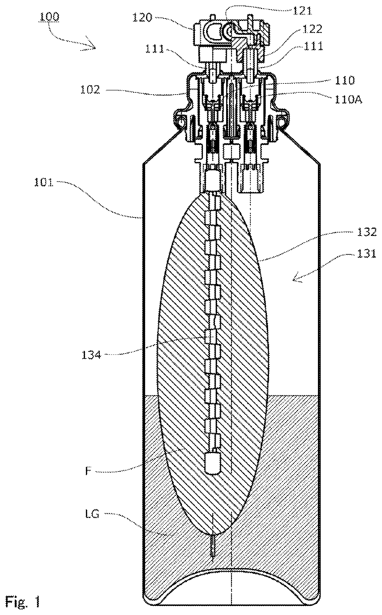
[0036]Flow path diameter of the valve 110 for the content F: 0.35 mm

[0037]Flow path diameter of the gas phase valve 110A: 0.35 mm

[0038]Liquefied gas: HFO-1234ze

Example 2

[0039]Flow path diameter of the valve 110 for the content F: 2.00 mm

[0040]Flow path diameter of the gas phase valve 110A: 0.35 mm

[0041]Liquefied gas: HFO-1234ze

[0042]A common one-valve aerosol spray container was used as comparative examples.

example 2

[0052]Table 2 shows the test results of the aerosol product 100 according to the first embodiment using water as the content F, with varying flow path diameters of the valve 110.

TABLE 2Flow pathAveragediameter particleEjection(mm)Area ratioGassizepressureConditionLiquidGasLiquid / gastype(μm)(g)10.32  2%HFO-NotNot1234zeejectablemeasurable10.32  2%LPG28.132.10.1510.32  2%LPGNotNot0.39ejectablemeasurable10.32  2%DME15.447.220.352  3%HFO-19.635.91234ze20.352  3%LPG17.146.20.3930.42  4%HFO-20.45.91234ze40.452  5%HFO-22.165.61234ze50.52  6%HFO-21.065.21234ze622 100%HFO-33.945.51234ze622 100%LPG35.13.10.15622 100%LPG22.486.50.39622 100%DME55.496.2720.51600%HFO-33.765.91234ze820.353265%HFO-41.226.41234ze920.34444%HFO-58.065.91234ze

[0053]In Condition 1 to Condition 6, the flow path diameter of the gas phase valve 110A was 2.00 mm, while the flow path diameter of the valve 110 for the content F was increased stepwise, i.e., 0.3 mm, 0.35 mm, 0.4 mm, 0.45 mm, 0.5 mm, and 2.00 mm.

[0054]In Conditi...


PUM


Abstract

To provide a simple-structured aerosol product with few limitations on applicable liquids and capable of spraying a mist of fine particles without giving too much sensation of coldness. The aerosol container (101) includes a plurality of holding spaces by being partitioned and a plurality of valves (110) corresponding to the holding spaces. At least one of the plurality of holding spaces is a liquefied gas containing section (131) that holds a liquefied gas LG, and at least one of the plurality of valves (110) is a gas phase valve (110A) that ejects vaporized gas from the liquefied gas containing section (131).

Description

TECHNICAL FIELD[0001]The present invention relates to an aerosol product having a valve with a stem protruding from an aerosol container, and a nozzle that fits with the stem, and more particularly to an aerosol product that favorably sprays a mist of the content therein.BACKGROUND ART[0002]Aerosol products having a valve with a stem protruding from an aerosol container, and a nozzle that fits with the stem, are well known, and so are products that spray a mist of the contents in the container from the nozzle.[0003]The content is atomized as it is ejected from the outlet orifice. For spraying the mist of the content, generally, the amount of ejected content, the ejection pressure, and the nozzle outlet shape are designed suitably in accordance with the properties of the content so as to produce a favorable spray of mist by the expansion force of the liquefied gas near the outlet orifice.[0004]The ejection pressure of the content and the expansion force of the liquefied gas near the ...

Claims


Application Information

Patent Timeline
Patent Type & Authority Applications(United States)
IPC IPC(8): B65D83/66
CPCB65D83/66B65D83/62B65D83/752B05B7/0483B05B9/04
Inventor KAMIJYO, HOKUTOOGATA, KENYAMAMOTO, NAOKI
Owner TOYO AEROSOL IND CO LTD
Why Eureka
Try Eureka