Electro-optical device and electronic apparatus

a technology of optical devices and electronic devices, applied in the direction of 3d-image rendering, instruments, computing, etc., can solve the problems of difficult to secure sufficient brightness of display images, user viewing images, and difficulty in detecting stereoscopic effects clearly by viewers, so as to improve the brightness of display images

Active Publication Date: 2012-07-12
SEIKO EPSON CORP
View PDF4 Cites 2 Cited by
  • Summary
  • Abstract
  • Description
  • Claims
  • Application Information

AI Technical Summary

Benefits of technology

[0006]However, according to the technology which is disclosed in JP-A-2009-25436, a period in which a user can view the image in practice is limited to the second half period (that is, approximately half) in each of the right eye period and left eye period. Accordingly, there is a problem in that it is not easy to secure sufficient brightness of the display image. An advantage of some aspects of the invention is to improve the brightness of the display image while preventing the user from sensing the mixed state of the right eye image and left eye image.

Problems solved by technology

Since the right eye image and left eye image are mixed in the period when one of the right eye image and left eye image is changed to the other, it may be difficult for the viewer to sense the stereoscopic effect clearly when viewing the stereoscopic image (cross talk).
However, according to the technology which is disclosed in JP-A-2009-25436, a period in which a user can view the image in practice is limited to the second half period (that is, approximately half) in each of the right eye period and left eye period.
Accordingly, there is a problem in that it is not easy to secure sufficient brightness of the display image.
In addition, the resolution of the display image is lowered in the first writing period, however, since the gradation signal is provided to each of the pixel circuits corresponding to the scanning line other than the specified scanning line in the second writing period immediately after the first writing period, it is possible to make the lowered resolution of the display image difficult for the viewer to sense.

Method used


Image

  • Electro-optical device and electronic apparatus
  • Electro-optical device and electronic apparatus
  • Electro-optical device and electronic apparatus

Examples


first embodiment

A: FIRST EMBODIMENT

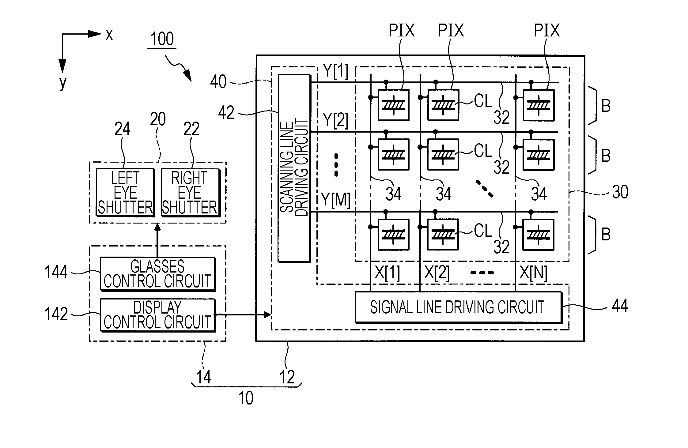
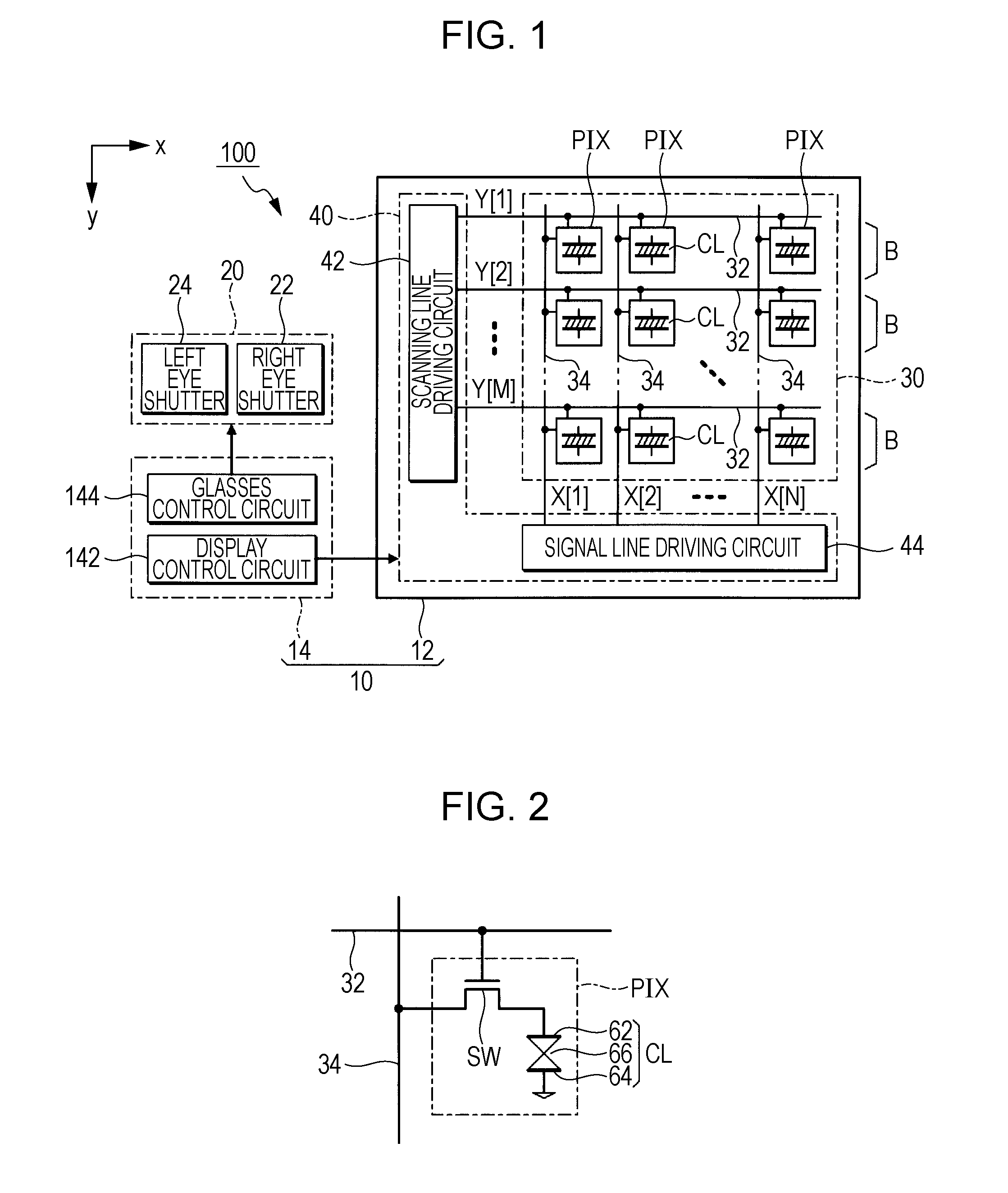
[0024]FIG. 1 is a block diagram of a stereoscopic display device 100 according to a first embodiment of the invention. The stereoscopic display device 100 is an electronic apparatus which displays a stereoscopic image which allows a viewer to sense a stereoscopic effect using an active-shutter system, and includes an electro-optical device 10 and stereoscopic glasses 20. The electro-optical device 10 alternately displays the right eye image GR and the left eye image GL in a time division manner.

[0025]The stereoscopic glasses 20 are glasses-type equipment worn by the viewer when viewing the stereoscopic image displayed using the electro-optical device 10. The stereoscopic glasses 20 include a right eye shutter 22 which is positioned at the front side of the right eye of the viewer and a left eye shutter 24 which is positioned at the front side of the left eye of the viewer. Each of the right eye shutter 22 and the left eye shutter 24 is controlled to be an open sta...

second embodiment

B: SECOND EMBODIMENT

[0045]The second embodiment of the invention will be described in below. In addition, in each embodiment which is exemplified in below, elements of which operations and functions are the same as those of the first embodiment will be given the same reference numerals and detailed descriptions thereof will be appropriately omitted.

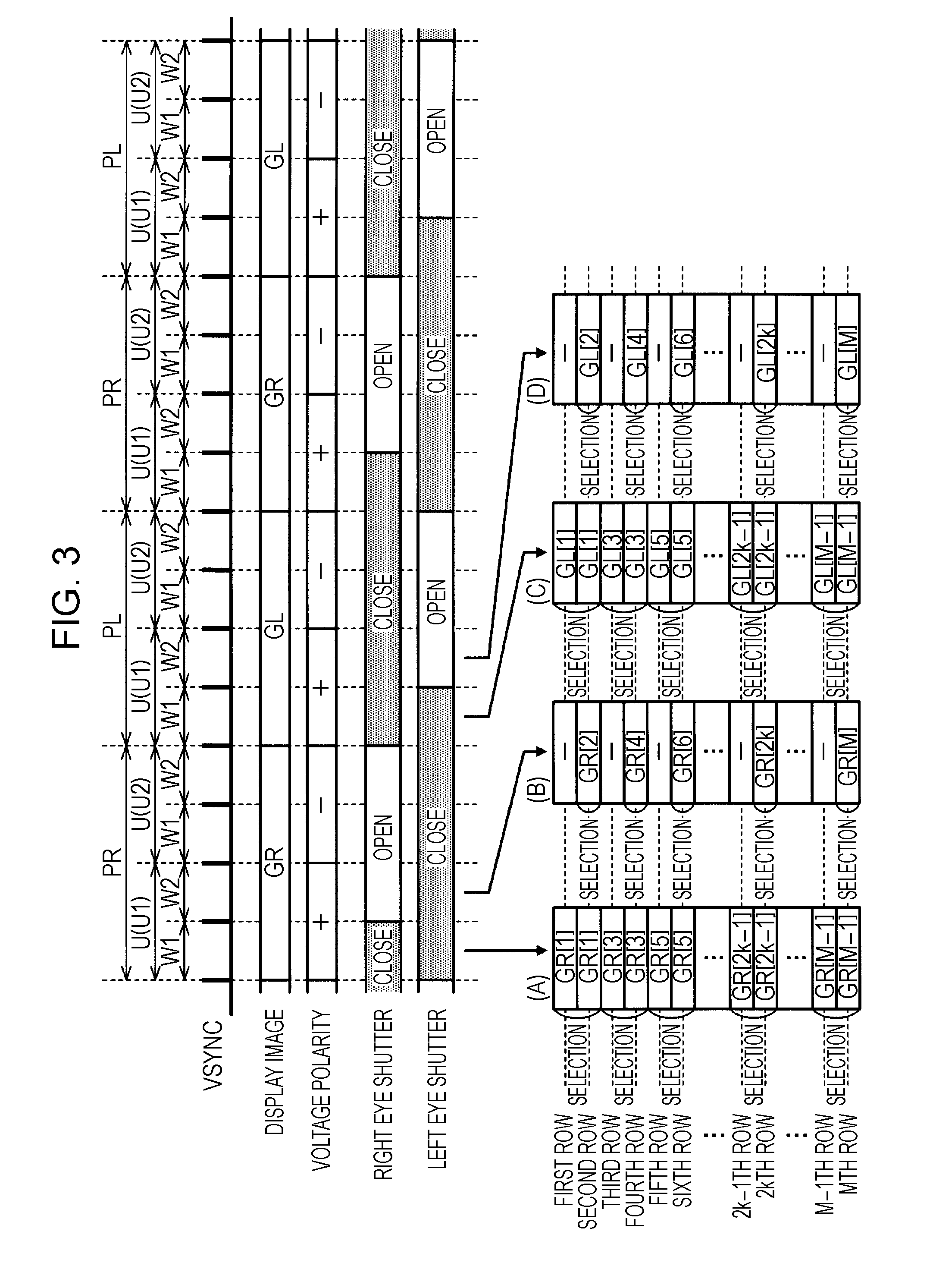
[0046]FIG. 5 is an explanatory diagram of an operation of a scanning line driving circuit 42 according to the second embodiment of the invention. In the first embodiment, the combination of a plurality of the scanning lines 32 (selection unit), which is simultaneously selected in each of the selection periods H(k) of the first writing period W1 was allowed to be common between the unit period U1 and the unit period U2. In the second embodiment, the combination of a plurality of the scanning lines 32, which is selected in the first writing period W1 is different between the unit period U1 and the unit period U2.

[0047]In detail, in the firs...

modified example 1

1. Modified Example 1

[0053]The number of scanning lines 32 which are simultaneously selected in a first writing period W1 (the number of scanning lines 32 which constitute a selection unit) are not limited to two which is exemplified above. When the number of the scanning lines 32 which constitutes the selection unit are generalized to H lines, each unit period U is divided into H writing periods of W1 to WH. In addition, in the initial first writing period W1 among each unit period, the selection unit (H scanning lines 32) is sequentially and simultaneously selected in each of K selection periods H(1) to H(k) (K=M / H). In addition, a potential VG corresponding to the specified gradation of each pixel which corresponds to the specified scanning line among a right eye image GR and left eye image GL is supplied to each pixel circuit PIX in the selection unit. Further, in each writing period Wh (h=2 to H) after a second row in the unit period U, one scanning line 32 of hth row in the se...


PUM


Abstract

A plurality of pixel circuits include liquid crystal elements which are arranged corresponding to each intersection of a plurality of scanning lines and a plurality of signal lines, and display a gradation corresponding to a gradation signal of the signal line at the time of selecting the scanning line. A driving circuit sequentially selects the plurality of scanning lines as a selection unit in a first writing period of a right eye period, supplies a gradation signal corresponding to a specified gradation of a right eye image which corresponds to a specified scanning line in the selection unit to each pixel circuit, and sequentially selects a scanning line other than the specified scanning line, and supplies a gradation signal which corresponds to the specified gradation corresponding to the specified gradation to each pixel circuit, in a second writing period.

Description

BACKGROUND[0001]1. Technical Field[0002]The present invention relates to a technology which displays a right eye image and left eye image to which a relative parallax is applied, in order to make a viewer sense a stereoscopic effect.[0003]2. Related Art[0004]In the related art, a stereoscopic method of a frame sequential method in which the right eye image and left eye image are alternately displayed in a time division manner has been proposed. Since the right eye image and left eye image are mixed in the period when one of the right eye image and left eye image is changed to the other, it may be difficult for the viewer to sense the stereoscopic effect clearly when viewing the stereoscopic image (cross talk). For example, a technology is disclosed in JP-A-2009-25436, in which a viewer is not allowed to view an image by making both a right eye shutter and left eye shutter be shut in the period when one of the right eye image and left eye image is changed to the other (that is, a tim...

Claims


Application Information

Patent Timeline
Patent Type & Authority Applications(United States)
IPC IPC(8): G06T15/00H04N13/122
CPCH04N13/0438H04N13/0018G02B27/2264H04N13/0497G09G3/003G09G3/3611G09G2310/0205G02B27/2242H04N13/341H04N13/398H04N13/122G02B30/36G02B30/24
Inventor ITO, AKIHIKO
Owner SEIKO EPSON CORP
Why Eureka
Try Eureka