Air-Oil Heat Exchanger

Active Publication Date: 2020-06-25
SAFRAN AERO BOOSTERS SA
View PDF18 Cites 0 Cited by
  • Summary
  • Abstract
  • Description
  • Claims
  • Application Information

AI Technical Summary

Benefits of technology

The patent application helps improve the efficiency of heat exchange while reducing air flow pressure loss. This is particularly important for turbojet oil coolers where the cold source is very low temperature and readily available.

Problems solved by technology

Such a heat exchanger generates significant turbulences in the air flow.

Method used


Image

  • Air-Oil Heat Exchanger
  • Air-Oil Heat Exchanger
  • Air-Oil Heat Exchanger

Examples


Embodiment Construction

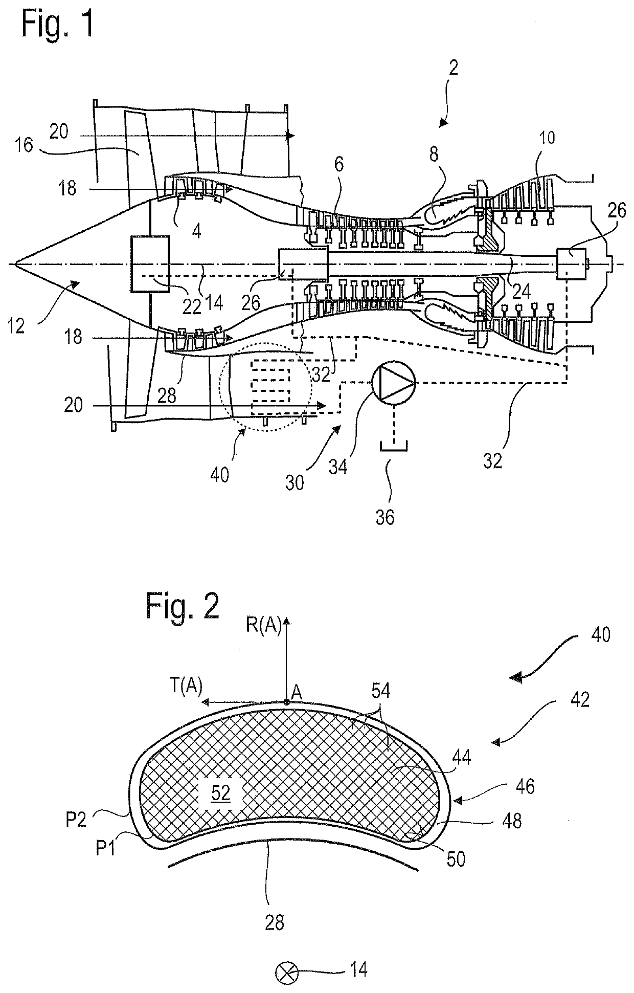
[0011]The present application aims to provide a heat exchanger that minimizes the aerodynamic losses in the air flow induced by the presence of the exchanger but also to reduce the aerodynamic losses inside the exchanger itself. The present application also aims to optimize the efficiency of the exchange of heat. The present application also aims to provide a simple and compact solution.

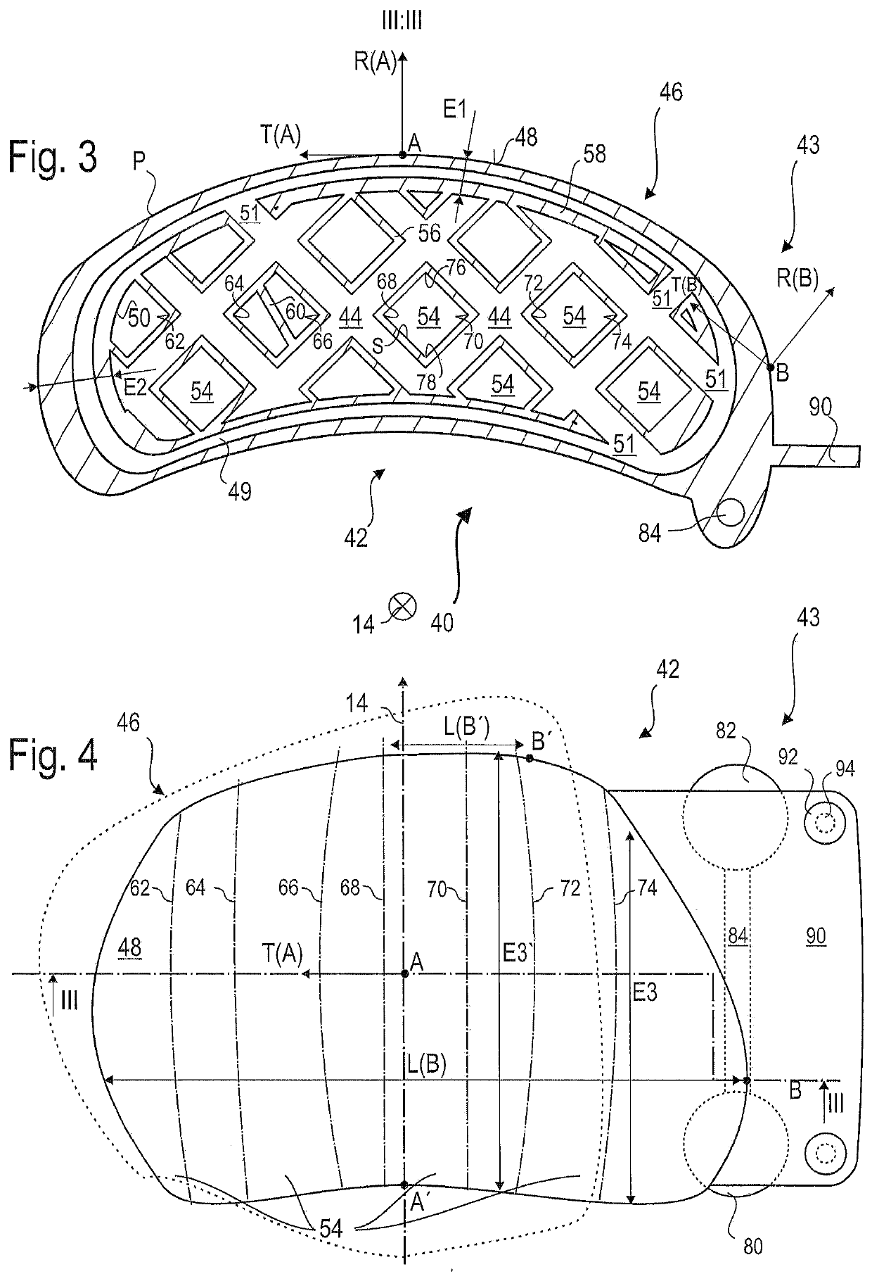
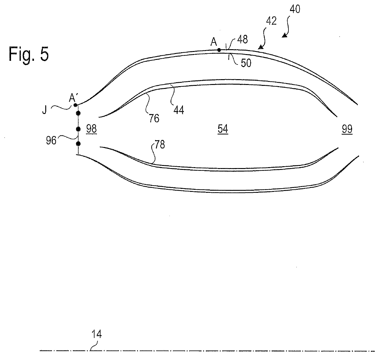
[0012]The subject-matter of the present application is a matrix for a heat exchanger, the matrix comprising: an envelope with an inner surface spatially delimiting a flow path for the flow of a first fluid, and an outer surface; the envelope being of generally arcuate shape defining an axial direction which is the main flow direction of the first fluid, and a radial direction and a circumferential direction; the outer surface defining an outer outline of the matrix, as seen in a plane perpendicular to the main direction; and a network extending in the bushing and in which the second fluid flows; wher...


PUM


Abstract

A matrix for exchanging heat between a first fluid and a second fluid, in particular for an air-oil application in a turbine engine, includes an envelope defining a flow path of the first fluid and a network extending into the flow path and in which the second fluid flows. Along the axis defined by the curvature of the matrix, the dimensions of the envelope vary circumferentially (T(A)) and radially (R(A)). The matrix may be used with a heat exchanger.

Description

[0001]This application claims priority under 35 U.S.C. § 119 to Belgium Patent Application No. 2018 / 5939, filed 24 Dec. 2018, titled “Air-Oil Heat Exchanger,” which is incorporated herein by reference for all purposes.BACKGROUND1. Field of the Application[0002]The present application relates to the field of turbine engine heat exchangers. More specifically, the present application proposes a turbine engine air / oil heat exchanger.2. Description of Related Art[0003]The document US 2016 / 0108815 A1 discloses an air / oil exchanger for an aircraft. This exchanger comprises a body of substantially arcuate shape and provided with a plurality of cooling fins arranged in a plurality of radial stages. Between two successive radial stages of fins are arranged circumferential passages for the oil.[0004]Such a heat exchanger generates significant turbulences in the air flow.[0005]Although great strides have been made in the area of turbomachine heat exchangers, many shortcomings remain.DESCRIPTION...

Claims


Application Information

Patent Timeline
IPC IPC(8): F02C7/18F02C7/14B33Y10/00F01D25/12F02C3/04F02C9/18
CPCF05D2240/12F02C7/14F05D2220/323F02C9/18F05D2240/30F02C3/04F05D2300/6032F01D25/12B33Y10/00F02C7/18F05D2260/213F05D2260/202F05D2260/22141F28D21/00F28F9/00F05D2230/31F05D2250/73F28D1/0246F28F13/08F28F7/02B33Y80/00Y02T50/60
Inventor WEICKER, DAVIDVLEUGELS, ROELFELLIN, NICOLAS
Owner SAFRAN AERO BOOSTERS SA
Why Eureka
Try Eureka