
Power relay device and system

a power relay and relay technology, applied in the direction of safety/protection circuits, instruments, transportation and packaging, etc., can solve the problems of inconvenience of charging the laptop computer, the mobile terminals are not charged simultaneously,

Active Publication Date: 2020-06-25
LG ELECTRONICS INC
View PDF0 Cites 5 Cited by
  • Summary
  • Abstract
  • Description
  • Claims
  • Application Information

AI Technical Summary

Benefits of technology

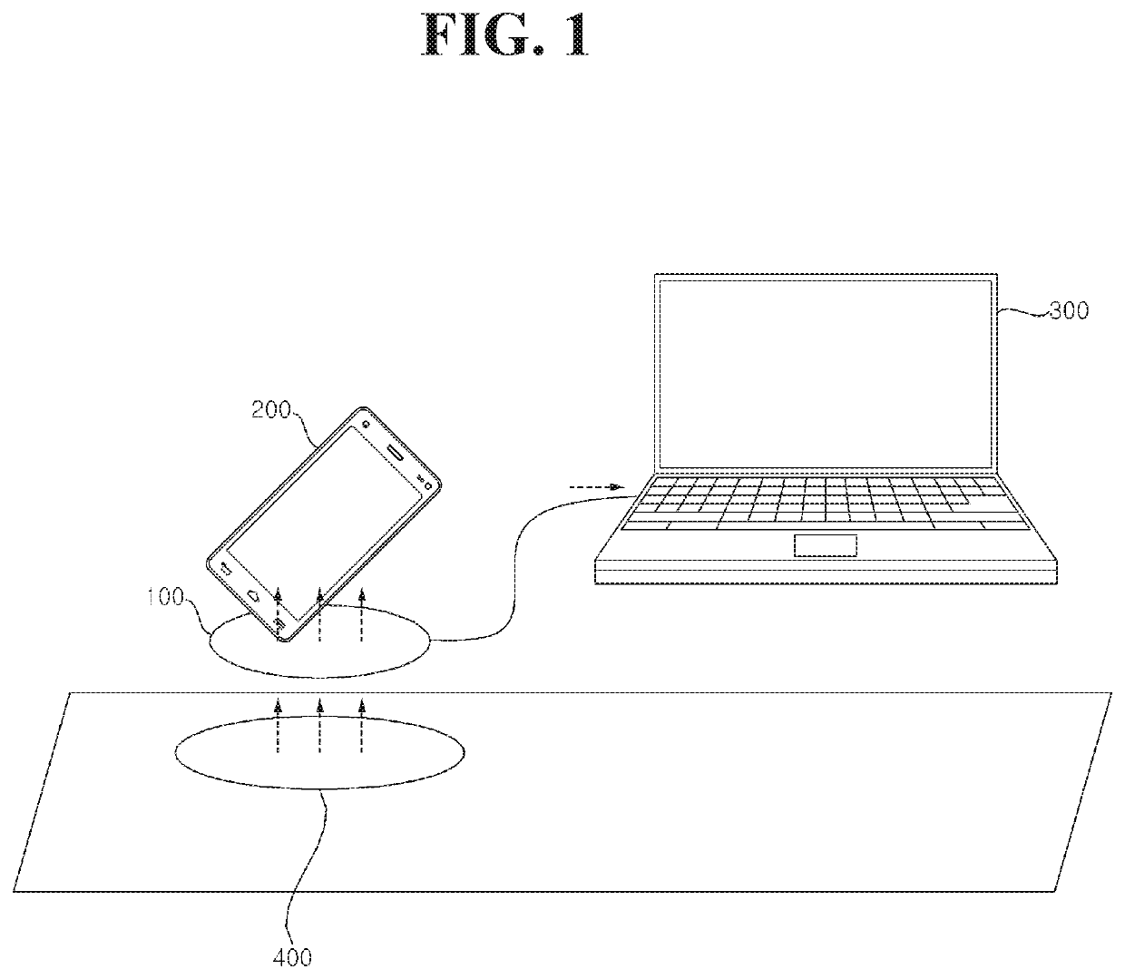
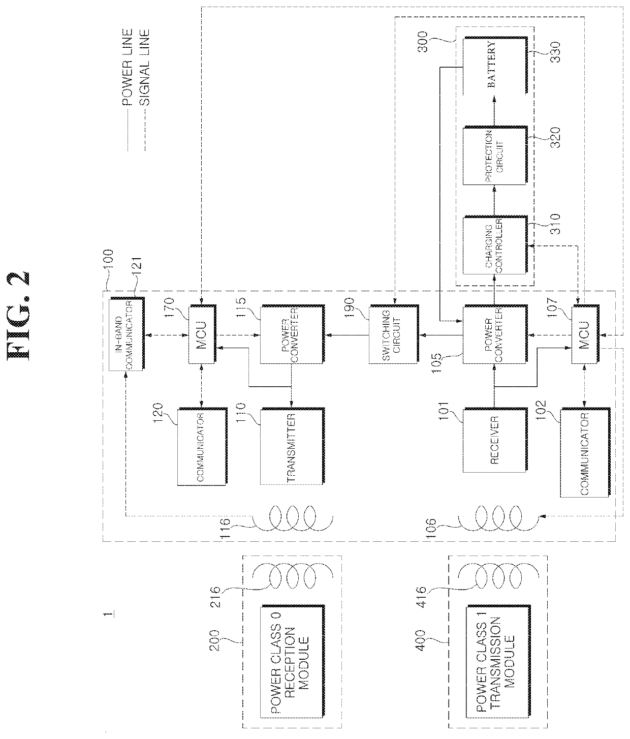
This present disclosure is about a power relay device that can charge multiple mobile devices. The device contains two power converters that can provide power of different levels to different mobile devices. The technical effect of this device is to provide efficient and flexible power supply for multiple mobile devices.

Problems solved by technology

In this case, when a single user has a plurality of mobile terminals, it is inconvenient in that the mobile terminals are not simultaneously charged.
For example, when a user intends to charge both a laptop computer and a smartphone, he or she experiences inconvenience of charging the laptop computer and the smartphone using separate respective charging devices.

Method used


Image

  • Power relay device and system
  • Power relay device and system
  • Power relay device and system

Examples


Embodiment Construction

[0016]Reference will now be made in detail to exemplary embodiments of the present disclosure, examples of which are illustrated in the accompanying drawings. The suffixes “module” and “unit” of elements herein are used for convenience of description and thus can be used interchangeably, and do not have any distinguishable meanings or functions. In the following description of the at least one embodiment, a detailed description of known functions and configurations incorporated herein will be omitted for the purpose of clarity and for brevity. The features of the present disclosure will be more clearly understood from the accompanying drawings and should not be understood to be limited by the accompanying drawings, and it is to be appreciated that all changes, equivalents, and substitutes that do not depart from the spirit and technical scope of the present disclosure are encompassed in the present disclosure.

[0017]It will be understood that, although the terms “first”, “second”, “t...


PUM


Abstract

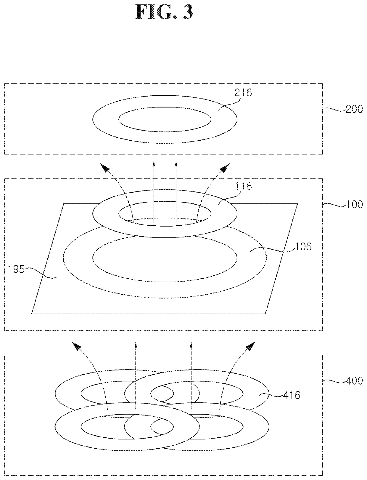
A power relay device includes a power receiver configured to wirelessly receive power of a first class when coupled with a wireless power transmission device, a first power converter configured to convert power supplied from the power receiver into a form appropriate for a first mobile terminal, a second power converter configured to receive power from the first power converter and to convert the power into power of a second class, and a power transmitter configured to wirelessly transmit the power of the second class to a second mobile terminal.

Description

CROSS-REFERENCE TO RELATED APPLICATION[0001]This application claims the priority benefit of Korean Patent Application No. 10-2018-0140517, filed on Nov. 15, 2018 in the Korean Intellectual Property Office, the disclosure of which is incorporated herein by reference into the present application.BACKGROUND OF THE INVENTION1. Field of the Invention[0002]The present disclosure relates to a power relay device and system.2. Description of the Related Art[0003]A wireless charger for a mobile terminal is commercially available. A conventional wireless charger is capable of charging a single mobile terminal but use thereof to charge a plurality of mobile terminals has not been considered. In this case, when a single user has a plurality of mobile terminals, it is inconvenient in that the mobile terminals are not simultaneously charged. For example, when a user intends to charge both a laptop computer and a smartphone, he or she experiences inconvenience of charging the laptop computer and th...

Claims


Application Information

Patent Timeline
Patent Type & Authority Applications(United States)
IPC IPC(8): H02J50/40H02J50/10H02J7/02H02J7/00
CPCH02J50/40H02J7/0027H02J50/10H02J7/025H02J50/12H02J7/00304H02J7/00308H02J13/00022G06F1/266Y04S40/121Y04S40/126Y02B90/20H04B5/79H04B5/263H02J50/50H02J7/0013H02J50/80
Inventor LEE, JIHYUNLEE, SEONGHUNKWAK, BONGSIKPARK, JOONHOKIM, SUNGKYU
Owner LG ELECTRONICS INC
Learn More