Method of sampling an analogue radiofrequency signal

Active Publication Date: 2009-12-15
STMICROELECTRONICS SRL
View PDF6 Cites 6 Cited by
  • Summary
  • Abstract
  • Description
  • Claims
  • Application Information

AI Technical Summary

Benefits of technology

[0038]Thus, passing through an intermediate frequency increases constraints on the circuit concerning matching of the I and Q channels to guarantee the elimination of the image frequency. Therefore, this invention is aimed at proposing a new sampling method for an analog radiofrequency signal, this method also filtering the analog signal such that the sampled signal represents a filtered version of the analog signal, which overcomes the disadvantages of classical solutions. In particular, this invention is intended to overcome the problem related to low frequency noise at 1 / f while limiting problems of the image power to be eliminated. This invention is also intended to propose a solution that optimizes the possibility of integrating radiofrequency reception systems and which in particular maintains the advantages related to the use of filters described previously with reference to FIG. 2 and subsequent figures.

Problems solved by technology

However, when it is required to respect the constraints mentioned above in order to reduce manufacturing costs, each of these architectures, namely the “low-IF” or “zero-IF” introduces distinct problems.
One disadvantage of this architecture is in the production of low-pass filters.
The production of amplifiers necessary to make these filters is complex and requires the use of expensive technological options such as double oxide or high density capacitances.
Thus in integrated circuits, it is usually not possible to integrate such a filter on the same circuit as the circuit containing the sampling circuit and the digital circuitry, without increasing manufacturing costs.
Also, due to this complexity, technology migrations providing the means of tending to a greater integration density of circuits will be difficult to apply for such an architecture since the size of filters cannot be reduced in the same way as transistors.
However, noise at 1 / f is a major problem for these architectures, in particular, when the integrated RF circuits of the reception system are made using CMOS technology.
Therefore the use of CMOS technology in the reception system means that the signal cannot be brought to base band before it has been digitized.
Therefore the zero-IF architecture cannot be used.
However, the difficulty to be taken into account lies in the aliasing phenomenon due to sampling.
Thus, it is impossible to have a useful signal with a frequency more than half the sampling frequency.
As we have already seen, use of CMOS technology introduces the problem of noise at 1 / f.
Consequently, this noise makes it impossible to bring the signal into the base band.
As the distance from the zero frequency decreases, the noise due to MOSs increases.
However, filtering would no longer be symmetric.
The result would then be imaginary filters in which the I and Q channels would have to be mixed before the filters could be used, which introduces serious problems when it is required to make digital corrections for bad matching of the channels.
Such a compromise will be difficult to find, for example for adaptation of such a receiver to the GSM (Global System for Mobile Communications) Standard or the UMTS (Universal Mobile Telecommunication System) standard.
A signal offset from the filter would then be excessively modified.
Therefore, the use of this architecture is limited for standards stricter than Bluetooth.
Another problem of this architecture is the image frequency.
It is then more difficult to eliminate the image frequency and to find the required information using the I and Q channels.

Method used


Image

  • Method of sampling an analogue radiofrequency signal
  • Method of sampling an analogue radiofrequency signal
  • Method of sampling an analogue radiofrequency signal

Examples


Embodiment Construction

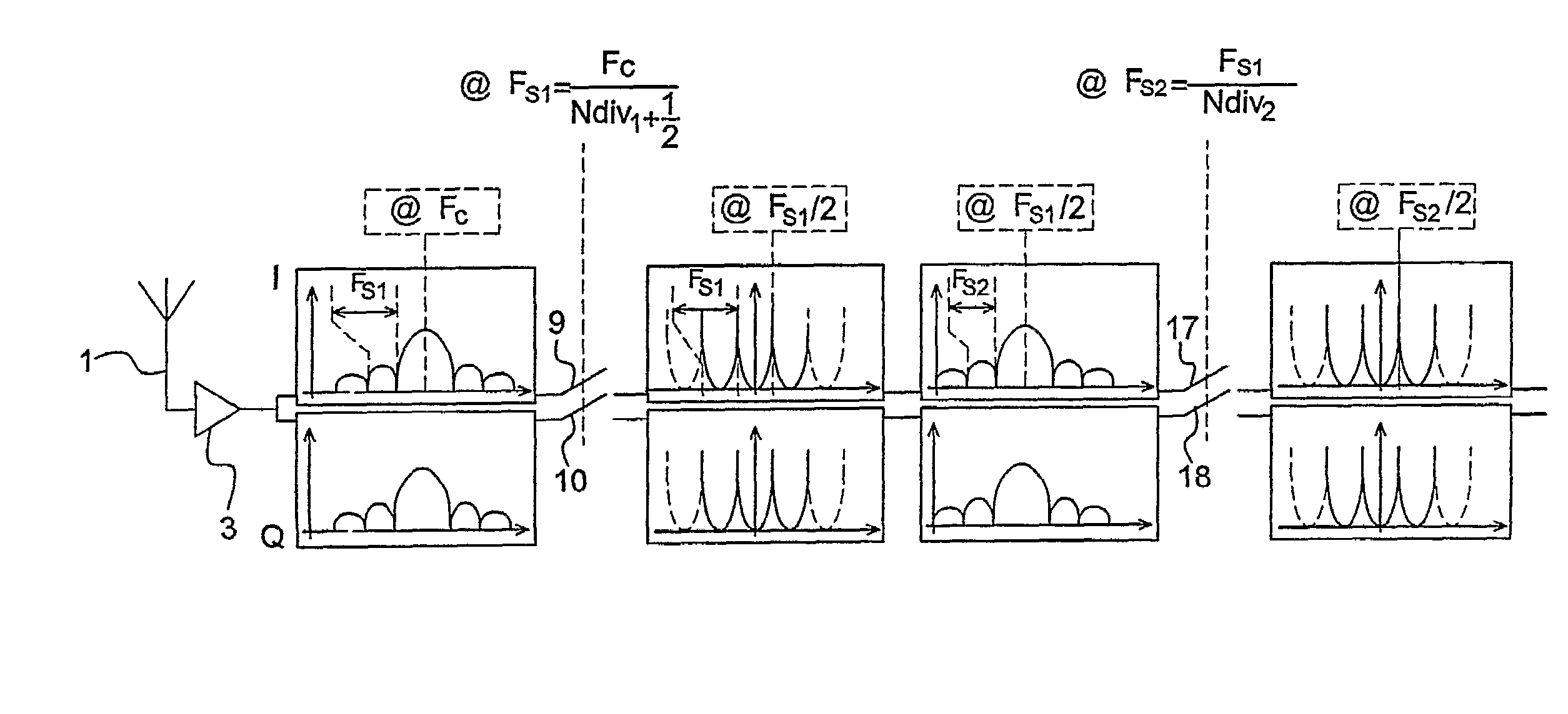
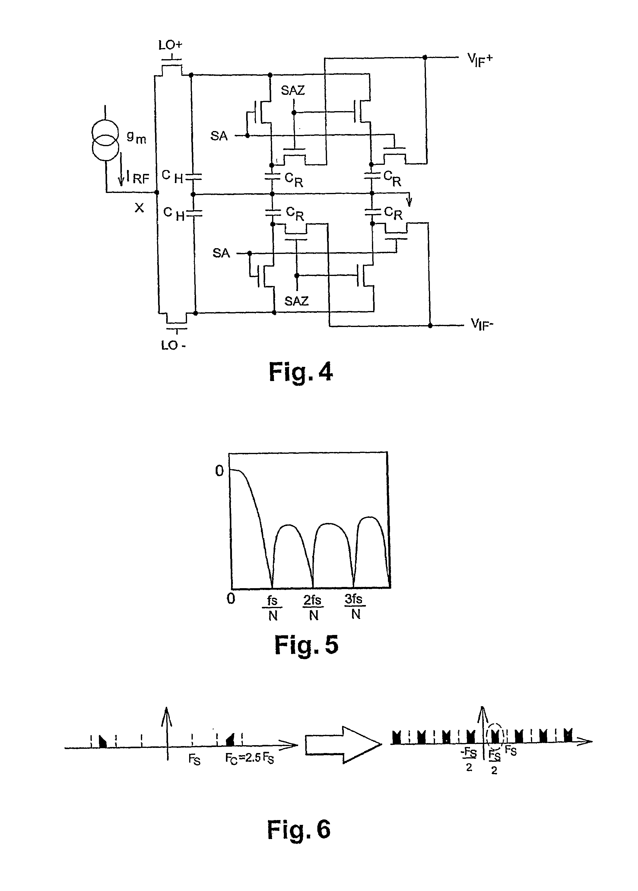
[0061]Thus, this invention is aimed as reusing sampling and filtering techniques described above, but according to the invention, it is proposed to bring the useful signal to be processed to a particular predetermined frequency, chosen as being half of the sampling frequency. This particular frequency is attractive for several reasons that will become clear from the following description made with reference to FIG. 6. Firstly, to bring the useful signal after sampling to half the sampling frequency, the ratio between the carrier frequency of the signal Fc and the sampling frequency Fs needs to be equal to Ndiv1+½, the term Ndiv1 being defined as an integer number. Thus, the following relation needs to be respected: Fc=(Ndiv1+½)·Fs.

[0062]According to the example in FIG. 6, Ndiv1 is taken equal to 2. The spectrum of the signal located around Fc=2.5Fs is shown at the left of the figure. After sampling, as shown on the spectrum at the right of the figure, the signal is folded to half of...


PUM


Abstract

A method for sampling an analogue radiofrequency signal comprising reception of the analogue radiofrequency signal, sending of the received signal on two analogue channels, each channel performing a first signal sampling operation, including a filtering step eliminating signal frequencies that could fold on the useful signal during sampling such that the sampled signal represents a filtered version of the received signal, wherein the sampling frequency is taken to be equal to the frequency of the signal carrier divided by a factor Ndiv1+½, Ndiv1 being an integer number, to bring the useful signal to half of the sampling frequency after sampling.

Description

BACKGROUND OF THE INVENTION[0001]1. Field of the Invention[0002]This invention relates to the radiofrequency reception field in general. More precisely, the invention relates to a method of sampling an analog radiofrequency signal and a device using this method. One particular example application of this invention is the mobile radiocommunication field that typically uses several communication channels within an allocated frequency band, for example radiocommunication systems according to the GSM (Global System Mobile) standard that use a 25 MHz frequency band centered on the 947.5 MHz frequency.[0003]This invention more particularly relates to reception of information which, in such systems, needs be done by extracting only the frequencies of the channel considered to be received, called the useful channel, from the entire frequency band.[0004]The useful channel is recovered by using filtering techniques at the receiver end to eliminate all frequencies located outside the useful ch...

Claims


Application Information

Patent Timeline
IPC IPC(8): H04B1/30
CPCH04B1/0025H04B1/28
Inventor JOET, LOICSAIAS, DANIELANDRE, ERIC
Owner STMICROELECTRONICS SRL
Why Eureka
Try Eureka