Vehicle drive control system, motor control device and a method for drive control of a vehicle
- Summary
- Abstract
- Description
- Claims
- Application Information
AI Technical Summary
Benefits of technology
Problems solved by technology
Method used
Image
Examples
first embodiment
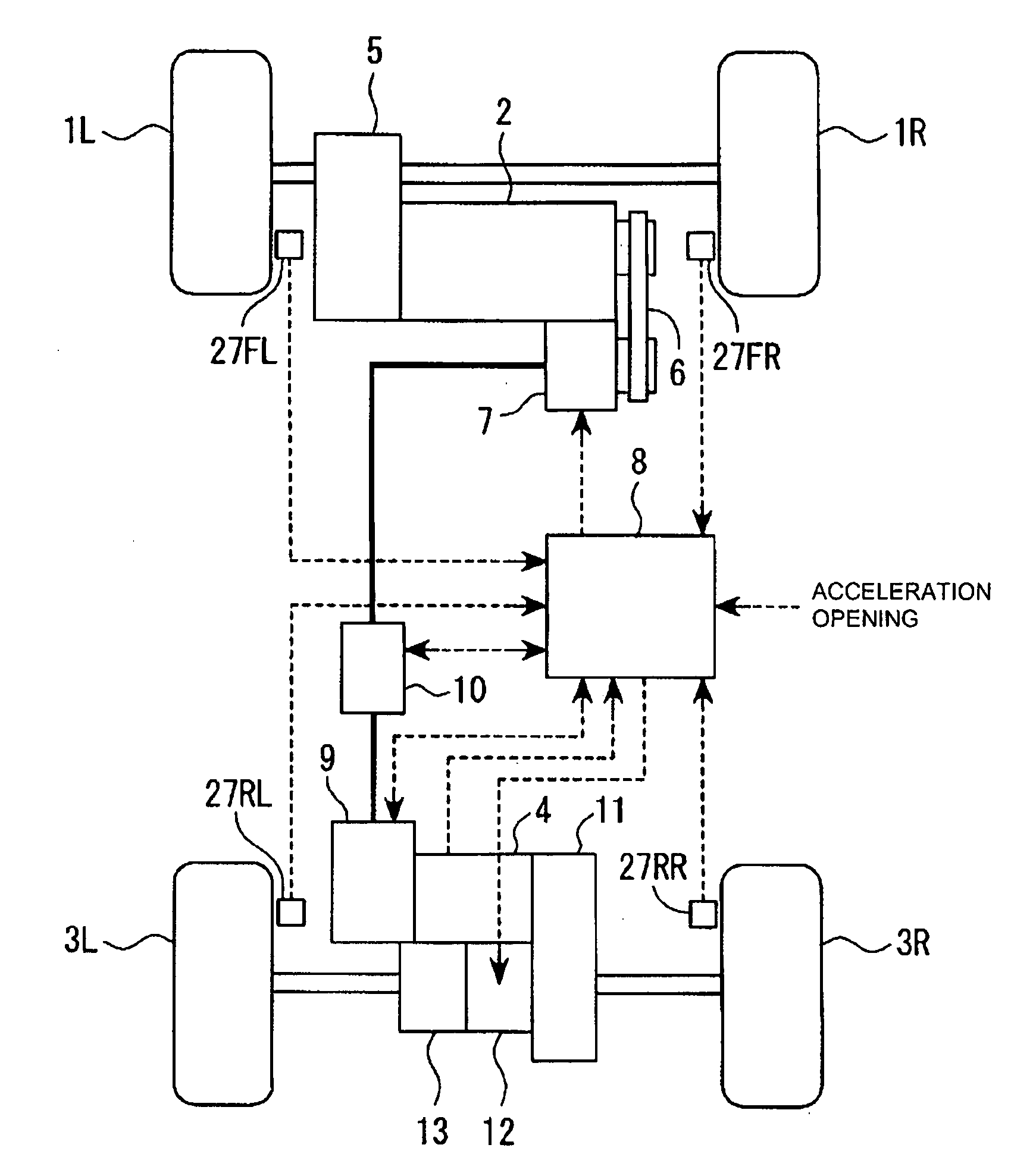
[0069]Operation of the invention will be described with reference to the timing chart shown in FIG. 7.
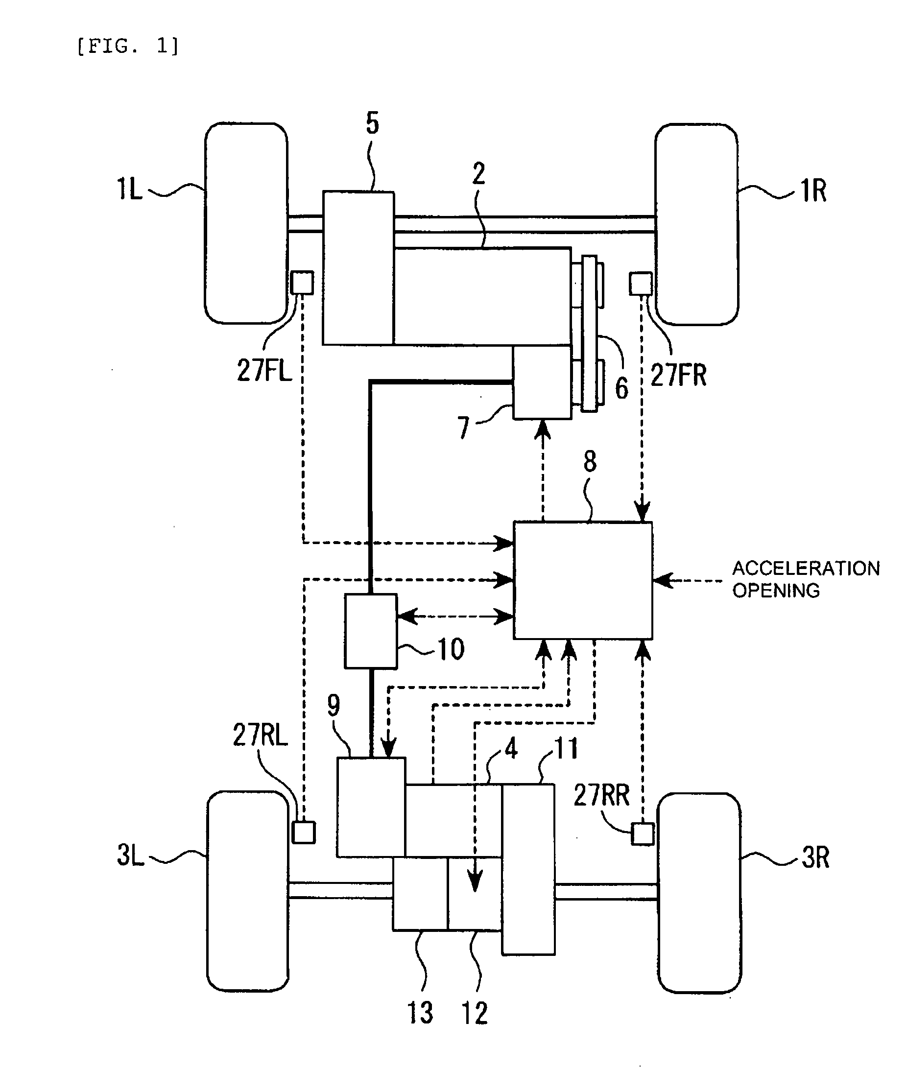
[0070]It is assumed that the 4-wheel drive mode stop condition is held at time t1 for the reason, for example, that no acceleration slip occurs in the front wheels. In this case, the 4WD controller 8 executes the motor brake control process shown in FIG. 6 and stops the motor field driving circuit in the step S1. The field reduction circuit is turned on to reduce the motor field current and, consequently, the motor field current Ifm gradually decreases.
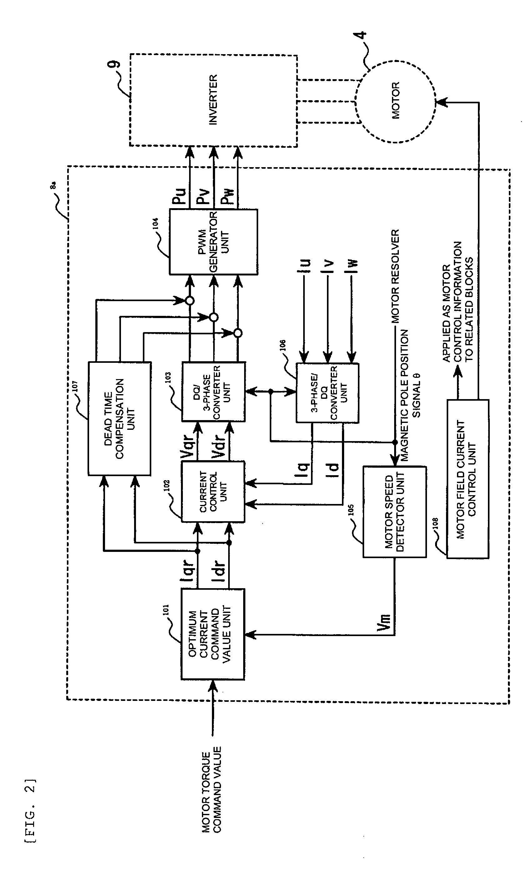
[0071]When the motor field current Ifm becomes smaller than the motor field current-threshold value IfmTH at time t2, the controller 8 executes the step S3 to turn on the switching elements Sx1 to Sx3 of the upper arm and to turn off the switching elements Sx4 to Sx6 of the lower arm, and starts the 3-phase short-circuiting mode in which the current is fed to the switching elements of the upper arm. At this time, the re-feeding of the...
second embodiment
[0083]the present invention will be described below. In this embodiment, the 3-phase short-circuiting mode by the upper arm and that by the lower arm are switched depending on temperature rise of the switching elements.
[0084]FIG. 8 is a flow chart showing a process flow of a motor brake control process executed by the 4WD controller 8 in the second embodiment. In the figure, like reference numerals are used for designating like portions of the motor brake control process of the first embodiment shown in FIG. 6, and description will be given placing emphasis on the portions that are not found in the process of the first embodiment.
[0085]When in step S6, the 4WD controller 8 determines that Nm>ΔNmTH, the controller proceeds to step S21. In step S21, temperature of the switching elements of the arm, which are in an on state, is measured. The temperature of the switching elements is measured using one of temperature sensors serving as temperature detecting means, which are provided on t...
third embodiment
[0096]the present invention will be described.
[0097]As already described in the first and second embodiments, the first 3-phase short-circuiting mode and the second 3-phase short-circuiting mode are alternately switched until the rotation speed of the motor reaches the target rotation speed after the 4-wheel drive mode stop condition holds. In the third embodiment, the first 3-phase short-circuiting mode and the second 3-phase short-circuiting mode are switched every time the motor brake control is performed.
[0098]FIG. 10 is a flow chart showing a process flow of a motor brake control process to be executed by the 4WD controller 8 in the third embodiment. In the figure, like reference numerals are used for designating like portions of the motor brake control process of the first embodiment shown in FIG. 4, and description will be given placing emphasis on the portions which are not found in the process of the first embodiment.
[0099]In step S31, the 4WD controller 8 determines whethe...
PUM
 Abstract
Description
Claims
Application Information
 - R&D
- Intellectual Property
- Life Sciences
- Materials
- Tech Scout
- Unparalleled Data Quality
- Higher Quality Content
- 60% Fewer Hallucinations
Browse by: Latest US Patents, China's latest patents, Technical Efficacy Thesaurus, Application Domain, Technology Topic, Popular Technical Reports.
© 2025 PatSnap. All rights reserved.Legal|Privacy policy|Modern Slavery Act Transparency Statement|Sitemap|About US| Contact US: help@patsnap.com


