Cooling System

a technology of cooling system and cooling chamber, which is applied in the direction of refrigeration components, mechanical equipment, light and heating equipment, etc., can solve the problems of simple loss of energy, process instability, and inability to use the energy released, so as to reduce the pressure of refrigerant, increase the suction pressure, and facilitate the removal of high-side heat exchangers

Active Publication Date: 2020-07-09
HEATCRAFT REFRIGERATION PRODS
View PDF0 Cites 1 Cited by
  • Summary
  • Abstract
  • Description
  • Claims
  • Application Information

AI Technical Summary

Benefits of technology

[0005]This disclosure contemplates an unconventional cooling system that uses energy released during expansion to drive a work recovery compressor. The work recovery compressor compress refrigerant from a load, thus concentrating heat. This disclosure also contemplates using a valve to stabilize the pressure of the refrigerant from the work recovery compressor before returning it to the system. As a result, the suction pressure of the system is increased, and system stability is improved. This increases the efficiency of the system. Certain embodiments of the system will be described below.
[0006]According to an embodiment, an apparatus includes a first expander, a flash tank, a first load, a first work recovery compressor, a valve, and a first compressor. The first expander expands a refrigerant. The flash tank stores a refrigerant from the expander. The first load uses the refrigerant from the flash tank to cool a space proximate the first load. The work recovery compressor compresses the refrigerant from the first load and is driven by the first expander. The valve reduces the pressure of the refrigerant from the work recovery compressor below a threshold. The first compressor compresses the refrigerant from the valve.
[0008]According to yet another embodiment, a system includes a high side heat exchanger, a first expander, a flash tank, a first load, a first work recovery compressor, a valve, and a first compressor. The high side head exchanger removes heat from a refrigerant. The first expander expands a refrigerant. The flash tank stores a refrigerant from the expander. The first load uses the refrigerant from the flash tank to cool a space proximate to the first load and is driven by the first expander. The valve reduces the pressure of the refrigerant from the work recovery compressor below a threshold. The first compressor compresses the refrigerant from the valve.
[0009]Certain embodiments provide one or more technical advantages. For example, an embodiment returns energy back to the system by using energy released during expansion in an expander to drive a work recovery compressor. As a result, the heat in the refrigerant is concentrated, making it easier for the high side heat exchanger to remove. As another example, an embodiment stabilizes the pressure of the refrigerant from the work recovery compressor before returning it to the system, thus increasing a suction pressure and making the system less susceptible to instability caused by the ambient temperature. As a result, the efficiency of the system is increased. Certain embodiments may include none, some, or all of the above technical advantages. One or more other technical advantages may be readily apparent to one skilled in the art from the figures, descriptions, and claims included herein.

Problems solved by technology

These systems, however, are unable to use the energy released during expansion.
Thus, the energy is simply lost.
However, this process can become unstable depending on ambient temperature.
If the ambient temperature is too high, the pressure of the system can reach dangerous levels.

Method used


Image

  • Cooling System
  • Cooling System
  • Cooling System

Examples


Embodiment Construction

[0016]Embodiments of the present disclosure and its advantages are best understood by referring to FIGS. 1 through 5 of the drawings, like numerals being used for like and corresponding parts of the various drawings.

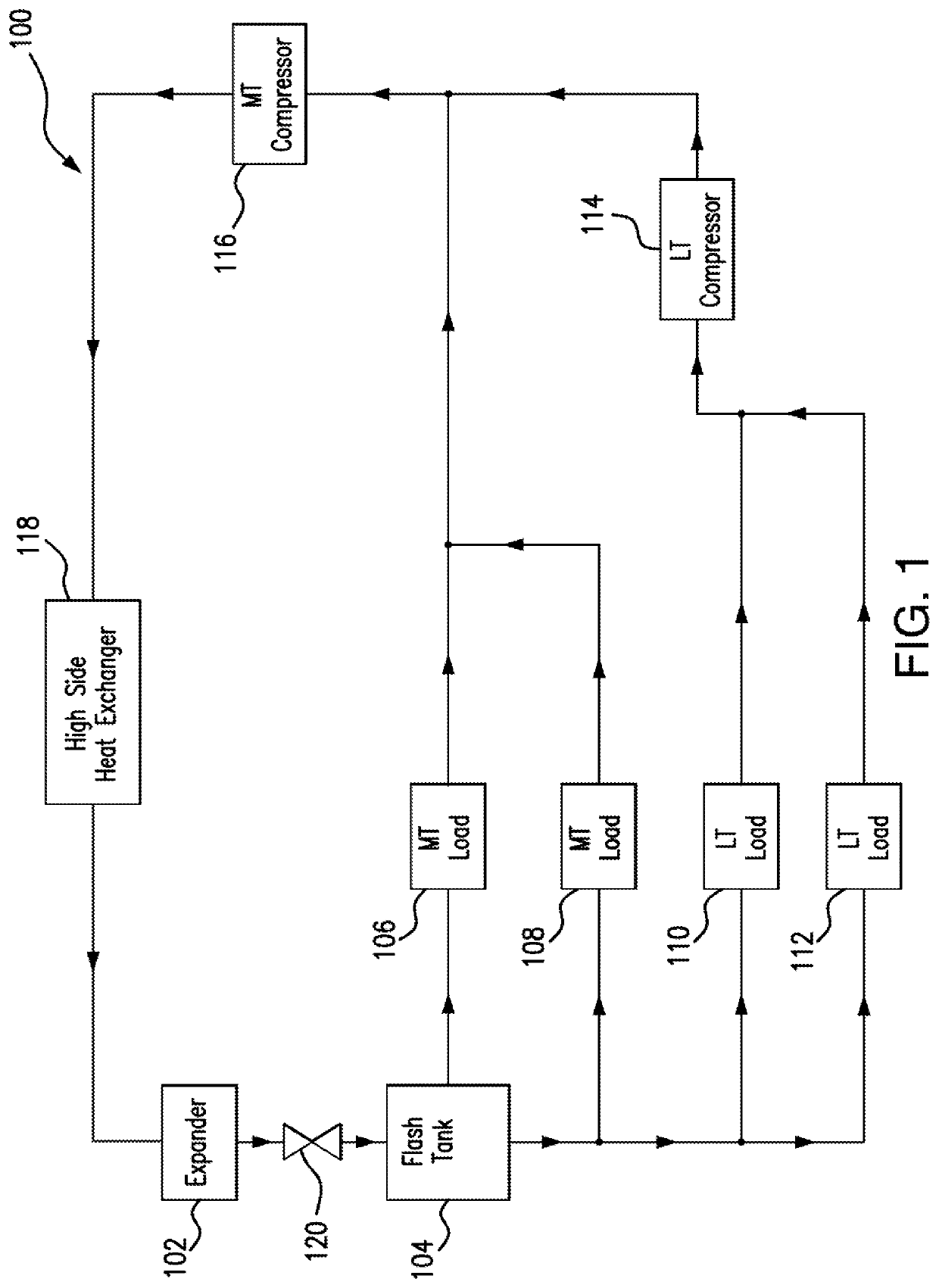
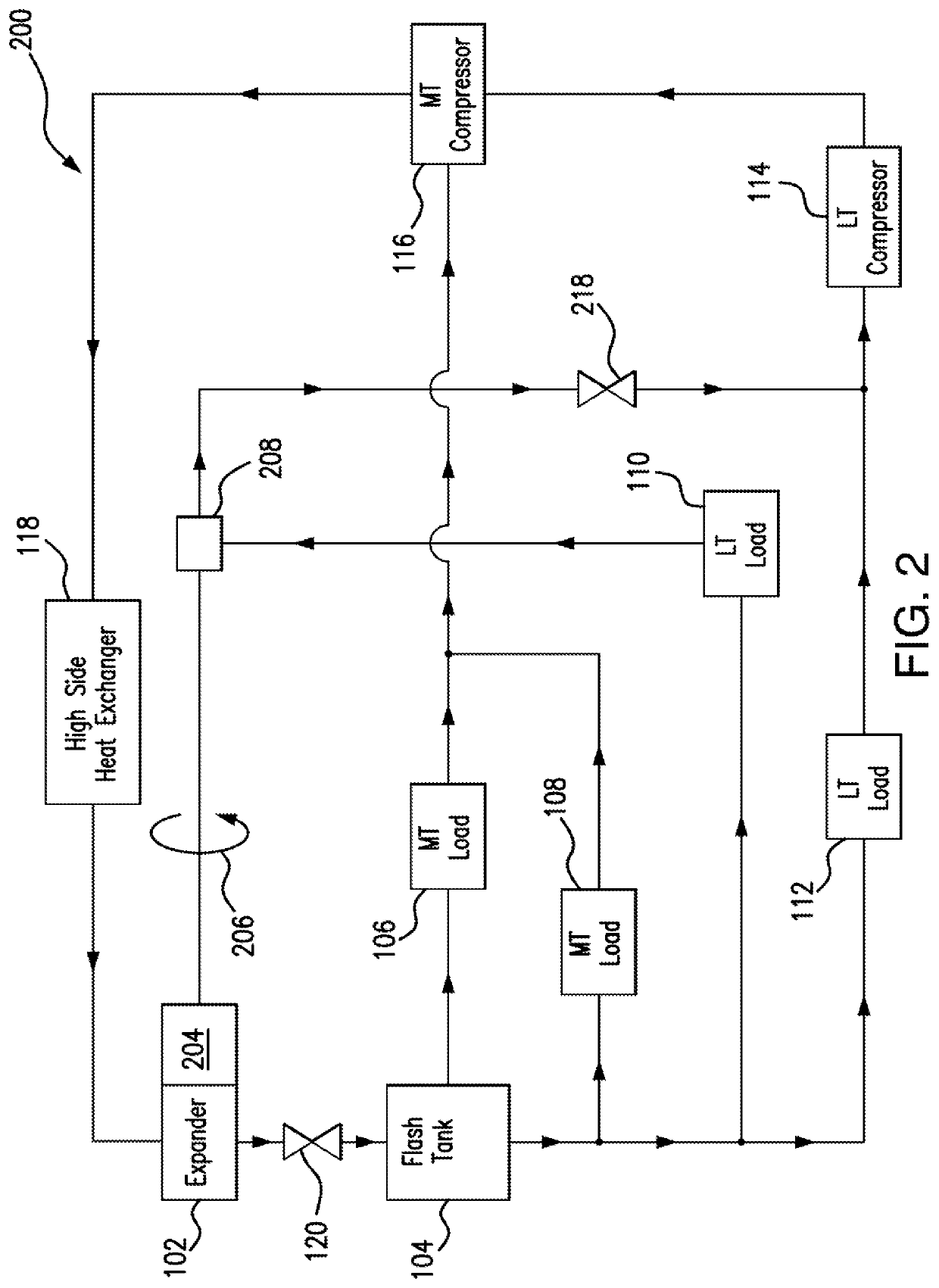
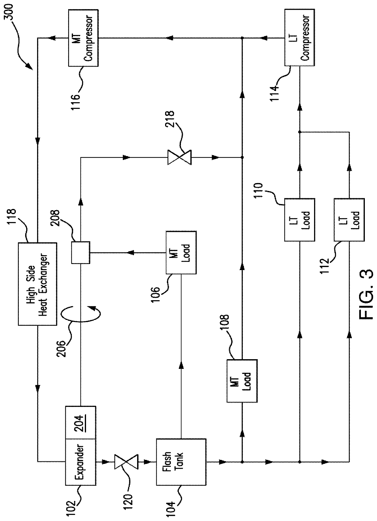
[0017]Refrigeration systems cycle refrigerant to cool spaces, such as residential dwellings, commercial buildings, and / or refrigeration units. Typical refrigeration systems include flash tanks, loads, compressors and a high side heat exchanger. The flash tank stores refrigerant, which is first cycled through the loads. The loads use the refrigerant to cool a space proximate the loads by absorbing heat. Thus, the refrigerant leaving the loads is warmer than the refrigerant entering the loads. The refrigerant is then directed to the compressors. The compressors compress the refrigerant to concentrate the absorbed heat so that the high side heat exchanger can more easily remove the heat from the refrigerant. The refrigerant next cycles through the high side heat exchanger, ...


PUM


Abstract

An apparatus includes a first expander, a flash tank, a first load, a first work recovery compressor, a valve, and a first compressor. The first expander expands a refrigerant. The flash tank stores a refrigerant from the expander. The first load uses the refrigerant from the flash tank to cool a space proximate the first load. The work recovery compressor compresses the refrigerant from the first load and is driven by the first expander. The valve reduces the pressure of the refrigerant from the work recovery compressor below a threshold. The first compressor compresses the refrigerant from the valve.

Description

TECHNICAL FIELD[0001]This disclosure relates generally to a cooling system, such as a refrigeration system.BACKGROUND[0002]Cooling systems are used to cool spaces, such as residential dwellings, commercial buildings, and / or refrigeration units. These systems cycle a refrigerant that is used to cool the spaces. As the refrigerant cycles, it is expanded and releases energy. This energy can be returned to the system to increase system efficiency.SUMMARY OF THE DISCLOSURE[0003]Refrigeration systems cycle refrigerant to cool spaces, such as residential dwellings, commercial buildings, and / or refrigeration units. Typical refrigeration systems include flash tanks, loads, compressors, and a high side heat exchanger. The flash tank stores refrigerant, which is first cycled through the loads. The loads use the refrigerant to cool a space proximate the loads by absorbing heat. Thus, the refrigerant leaving the loads is warmer than the refrigerant entering the loads. The refrigerant is then dir...

Claims


Application Information

Patent Timeline
Patent Type & Authority Applications(United States)
IPC IPC(8): F25B1/10F25B43/00
CPCF25B1/10F25B43/006F25B2400/13F25B31/00F25B2400/07F25B5/02F25B2400/14F25B41/20F25B2400/075F25B2400/23
Inventor SUN, XIZHA, SHITONG
Owner HEATCRAFT REFRIGERATION PRODS
Why Eureka
Try Eureka