LED lamp

a technology of led lamps and led tubes, which is applied in the direction of fixed installations, lighting and heating apparatus, lighting support devices, etc., can solve the problems of limited illuminating area of lamps and relatively concentrated heat generated by leds

Inactive Publication Date: 2011-08-02
FU ZHUN PRECISION IND SHENZHEN +1
View PDF2 Cites 0 Cited by
  • Summary
  • Abstract
  • Description
  • Claims
  • Application Information

AI Technical Summary

Benefits of technology

[0005]A conventional LED lamp comprises a heat sink and a plurality of LED modules having LEDs attached to an outer surface of the heat sink to dissipate heat generated by the LEDs. Generally, the outer surface of the heat sink is planar and the LEDs are arranged on the planar outer surface to form an area light source. When the LED lamp works, the area light source formed by the LEDs mounted on the planar outer surface of the heat sink radiates light at a same direction. As a result, the LED lamp has a restricted illuminating area and the heat generated by the LEDs is relatively concentrated.

Problems solved by technology

As a result, the LED lamp has a restricted illuminating area and the heat generated by the LEDs is relatively concentrated.

Method used


Image

  • LED lamp
  • LED lamp
  • LED lamp

Examples


Embodiment Construction

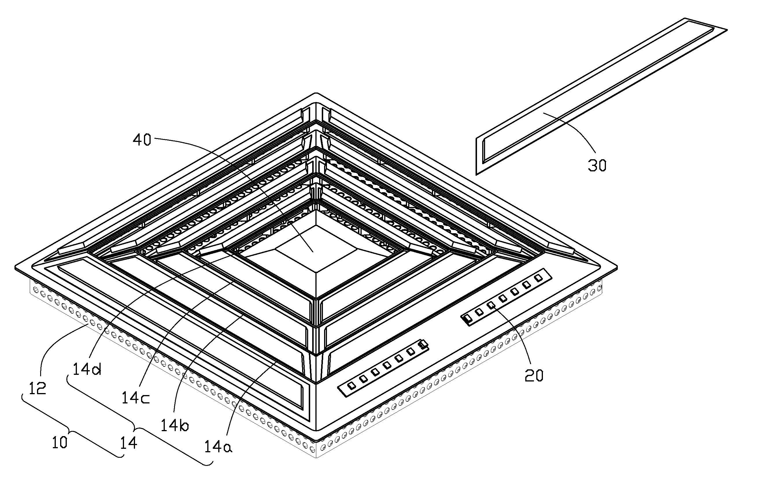
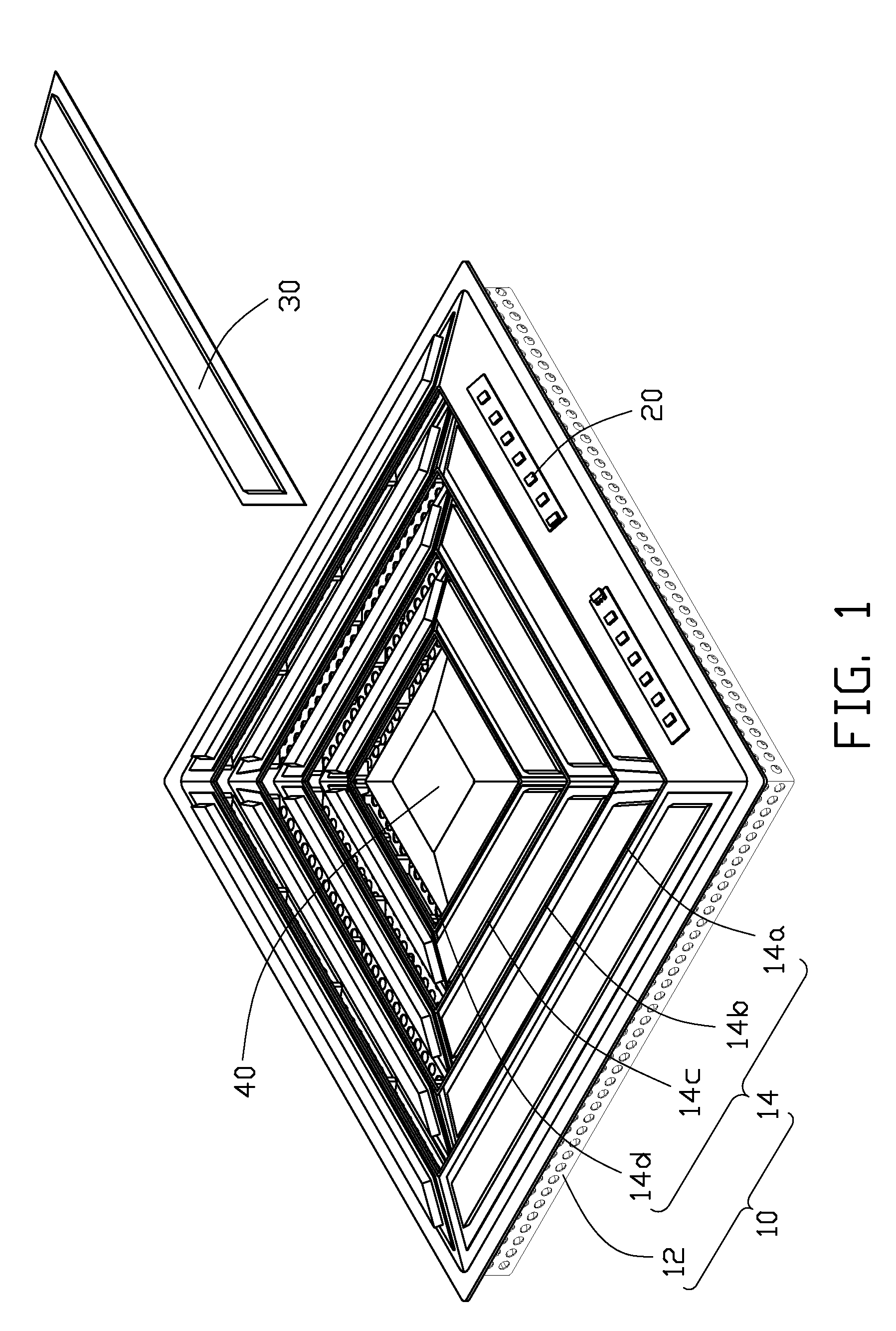
[0013]Referring to FIGS. 1-2, an LED lamp of the disclosure comprises a bracket 10, a number of LED modules 20 mounted on the bracket 10, a number of envelopes 30 covering the LED modules 20 and mounted on the bracket 10, and a driving circuit module 40 mounted on a center of the bracket 10 and electronically connecting with the LED modules 20.

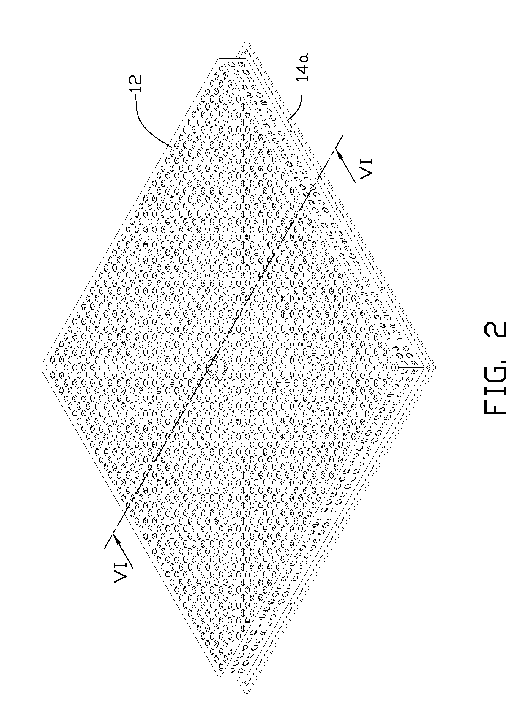
[0014]Referring to FIGS. 3-4 also, the bracket 10 is metallic and comprises a base 12 and a holding frame 14 mounted on the base 12. The base 12 comprises a rectangular top plate 120 and four sidewalls 122 extending downwardly from four edges of the top plate 120. A flange 124 extends outwardly from a bottom end of each of the four sidewalls 122. Each flange 124 is perpendicular to the corresponding sidewall 122. A number of through holes 126 are defined in both the top plate 120 and the sidewalls 122 of base 12 to dissipate heat of the LED lamp.

[0015]Referring to FIGS. 5-6 also, the holding frame 14 is fixed to a bottom of the base 12. The ho...


PUM


Abstract

An LED lamp includes a plurality of barrel-type holders and a plurality of LED modules mounted on an outer surface of each of the barrel-type holders. Each of the barrel-type holders has a small opening end and a large opening end opposite to the small opening end. The barrel-type holders are coaxial with each other, with a larger barrel-type holder enclosing a smaller barrel-type holder. The small opening ends of the barrel-type holders face downwardly, while the large opening ends face upwardly.

Description

BACKGROUND[0001]1. Technical Field[0002]The disclosure relates to light emitting diode (LED) lamps and, more particularly, to an LED lamp having a wide range of illumination angle.[0003]2. Description of Related Art[0004]The technology of LEDs has rapidly developed in recent years from indicators to illumination applications. With the features of long-term reliability, environment friendliness and low power consumption, the LED is viewed as a promising alternative for future lighting products.[0005]A conventional LED lamp comprises a heat sink and a plurality of LED modules having LEDs attached to an outer surface of the heat sink to dissipate heat generated by the LEDs. Generally, the outer surface of the heat sink is planar and the LEDs are arranged on the planar outer surface to form an area light source. When the LED lamp works, the area light source formed by the LEDs mounted on the planar outer surface of the heat sink radiates light at a same direction. As a result, the LED l...

Claims


Application Information

Patent Timeline
Patent Type & Authority Patents(United States)
IPC IPC(8): F21V21/00
CPCF21S8/02F21V15/01F21V29/75F21V29/74F21V29/004F21V19/001F21Y2101/02F21Y2103/003F21Y2103/10F21Y2115/10
Inventor ZHENG, SHI-SONG
Owner FU ZHUN PRECISION IND SHENZHEN
Why Eureka
Try Eureka