Transparent thin film antenna

a thin film antenna and transparent technology, applied in the direction of antennas, slot antennas, antennas, etc., can solve the problems of reducing the performance of the antenna, reducing etc., to improve the efficiency of the antenna, reduce ohmic loss, and increase the surface conductivity

Active Publication Date: 2007-06-19
GM GLOBAL TECH OPERATIONS LLC
View PDF6 Cites 49 Cited by
  • Summary
  • Abstract
  • Description
  • Claims
  • Application Information

AI Technical Summary

Benefits of technology

[0008]The present invention provides a method for improving the efficiency of an antenna having a surface formed of a transparent thin-film conducting material. Broadly, the method comprises: (a) determining values for current density distributed over areas of the surface of the transparent thin-film conducting material in which current flows as a result of operation of the antenna at a selected frequency; (b) identifying areas of the surface having concentrated current flow based on the determined values for current density; and (c) increasing surface conductivity in a portion of the areas of the surface identified as having concentrated current flow, thereby reducing ohmic loss and increasing antenna efficiency.
[0011]Once the areas having concentrated current flow are identified, portions of one or more of these areas are overlaid with an electrically conductive material to increase the surface conductivity, thereby reducing ohmic loss to improve the efficiency of the antenna
[0012]By determining values for current density in areas distributed over the entire surface of the thin-film, the areas having concentrated current flow can be identified easily. As a result, areas of the surface where conductivity is increased can be limited to the regions identified as having higher magnitudes of current density. Since areas where conductivity is increased become less transparent, the present method enables antenna efficiency to be increased in a more optimal and selective fashion, without unnecessarily obstructing the optical view through the thin-film surface of the antenna.
[0013]The present invention also includes antennas having improved efficiency resulting from the application of the above method. The efficiency of antennas having surfaces formed of transparent thin-film conducting material are improved by overlaying electrically conductive material over portions of areas of the surface identified as having concentrated current flow. Therefore, ohmic loss in the surface can be selectively reduced to improve antenna efficiency, without undesirably obstructing the optical view through the antenna.

Problems solved by technology

When transparent thin-films having these higher surface resistances are used as the conductive surfaces for an antenna, the performance of the antenna is diminished.
Without knowing the exact nature of the currents flowing on the surface of the thin-film antenna, the size of the areas where conductivity is increased can be made too large, thereby unnecessarily obstructing the optical view through a transparent antenna, or if areas of high current flow are not recognized and made more conductive, the resulting antenna will have a lower efficiency that could have otherwise been achieved.

Method used


Image

  • Transparent thin film antenna
  • Transparent thin film antenna
  • Transparent thin film antenna

Examples


Embodiment Construction

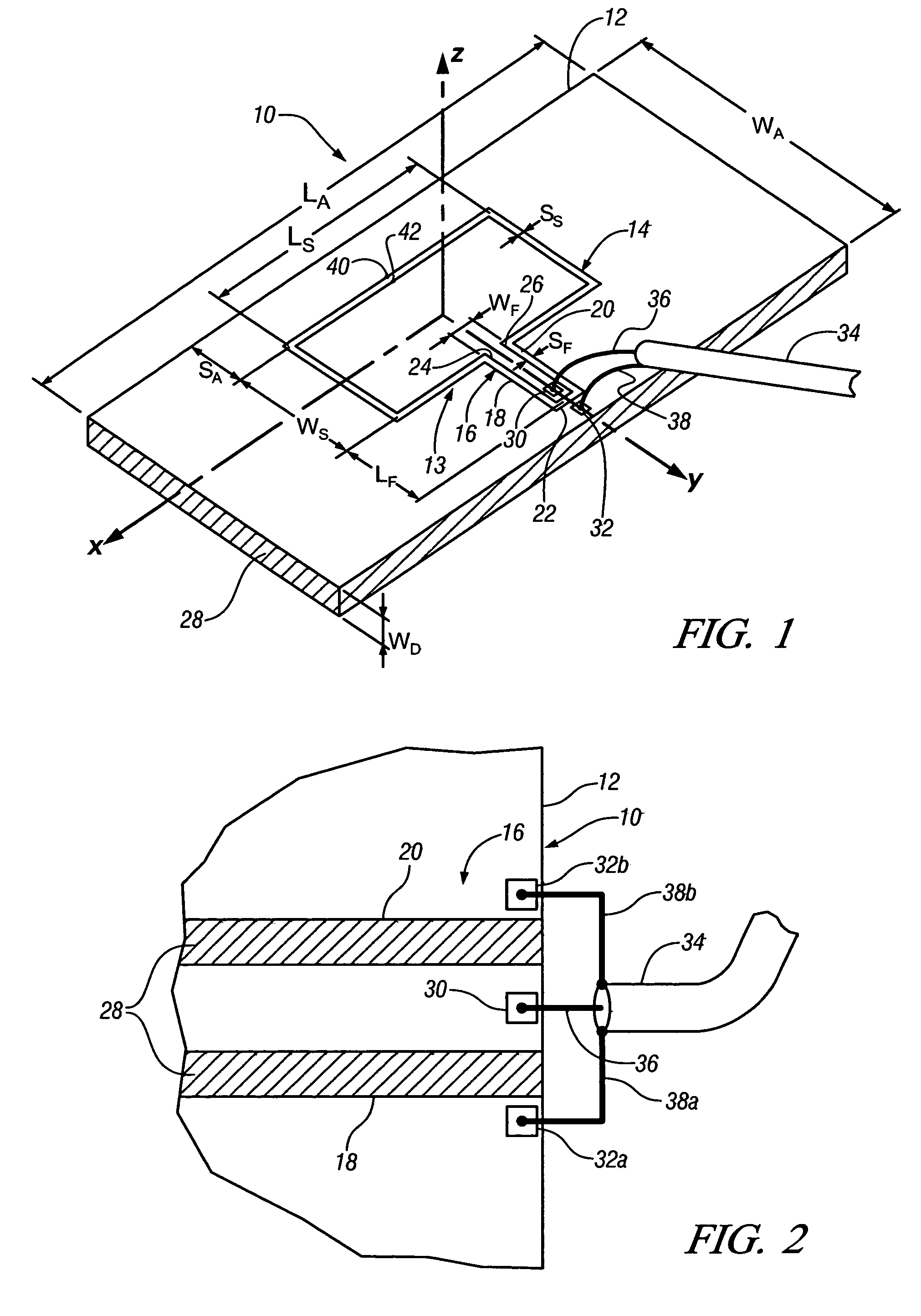
[0026]Turning now to the drawings, and referring first to FIG. 1, there is shown in diagram form, a perspective view of a thin-film antenna, generally designated as 10, which will be used to demonstrate the method of the present invention. Is should be noted that use of antenna 10 is intended only to be exemplary, as the method of the present invention can be applied to thin-film conducting surfaces of antennas having different forms and structures.

[0027]The thin-film antenna 10 is comprised of a sheet of transparent thin-film conducting material 12, having an aperture formed in its surface by the closed continuous slot designated generally by 13. The closed continuous slot 13 is comprised of two connected slot portions, a rectangular shaped slot portion designated generally by 14, which connects to a substantially U-shaped slot portion designated generally by 16. The slot of the U-shaped portion 16 is comprised of two essentially parallel slot sections 18 and 20, each connected to ...


PUM


Abstract

A method for improving the efficiency of antennas having transparent thin-film conductive surfaces, and antennas improved by the method are disclosed. For a selected frequency of antenna operation, values for surface current density in areas distributed over the surface of the thin-film are determined. Regions of the surface containing areas having concentrated current flow are identified based upon the determined values of current density. Antenna efficiency is improved by increasing conductivity in areas of the thin-film surface found to have concentrated current flow. The method enables the improvement of the efficiency of antennas having transparent thin-film conducting surfaces, without unnecessarily obstructing the optical view through the thin-film surfaces of the antennas.

Description

CROSS-REFERENCE TO RELATED APPLICATIONS[0001]This application is related to U.S. patent application Ser. No. 11 / 208,211 entitled “METHOD FOR IMPROVING THE EFFICIENCY OF TRANSPARENT THIN FILM ANTENNAS AND ANTENNAS MADE BY SUCH METHOD” filed on even date herewith and incorporated herein by reference.TECHNICAL FIELD[0002]The present invention is related to thin-film antennas, and more particularly to a method for improving the efficiency of antennas having surfaces formed of transparent thin-film conducting material, and antennas made by such method.BACKGROUND OF THE INVENTION[0003]The use of thin-film antennas has been gaining popularity in recent years. Thin-film antennas are generally formed by applying a thin layer of conductive material to sheets of plastic film such as polyester, and then patterning the resulting sheets to form the conductive surfaces of antennas. Alternatively, conductive material may also be deposited on plastic or other dielectric sheets in desired patterns to...

Claims


Application Information

Patent Timeline
Patent Type & Authority Patents(United States)
IPC IPC(8): H01Q1/32
CPCH01Q1/1271H01Q13/106
Inventor SONG, HYOK J.HSU, TSUNG YUANSIEVENPIPER, DANIEL F.TALTY, TIMOTHY J.HSU, HUI-PIN
Owner GM GLOBAL TECH OPERATIONS LLC
Why Eureka
Try Eureka