Spacer bead geometry for controlled sealing stability

a spacer bead and stability technology, applied in the direction of incadescent body mounting/support, gas-filled discharge tubes, incadescent envelopes/vessels, etc., can solve the problems of significant increase in cost, waste of lamps during inspection, and assembly subject to forces that are out of proportion, so as to achieve the effect of avoiding the instability of the envelop

Inactive Publication Date: 2008-01-08
CARLEY JAMES A
View PDF4 Cites 0 Cited by
  • Summary
  • Abstract
  • Description
  • Claims
  • Application Information

AI Technical Summary

Benefits of technology

[0010]A shaped bead structure provides a bottom sealing periphery adjacent a non-bonding portion. An upper portion may provide upper envelope stability and may or may not bond to the glass envelope. Even where upper bonding occurs, the provision of a section of the glass envelope free of bonding above the lower peripheral sealing provides a leveraged stability to the upper portion of the glass envelope.
[0011]The technique and geometry provided by the shaped bead structure can work in conjunction with structures which provide spacing between the upper bead and glass envelope or between the filament and uppermost bead. The use of two or more structures to provide a significant annular area of non-contact with the annular envelope can help to provide a structure which is non-complex to manufacture. A bead section having a peripherally outermost portion and a portion which is displaced significantly peripherally inward to prevent contact with the glass envelope. Where two of the bead sections are stacked with the portions which are displaced significantly peripherally inwardly adjacent each other, an annular space is formed. The annular space prevents glass envelope sealing with respect to a significant length of the glass envelope leaving it in tact and enabling it to “break” any vertically extending wetted interface. Where only the bottom bead is used for sealing, the space provides a halt to any vertical growth of the wetted sealing, while the remainder of the bead structure within the glass envelope provides displacement of the fill gas. By providing fill gas displacement, the bulb becomes more efficient in requiring less fill gas and in concentrating the heat generated by the filament into a more confined area, by lowering the convection volume and effective radiative surface area exposed to convective gas.
[0012]The bead structure of the invention can be used in conjunction with glass envelopes having a lens-type end and can also work in conjunction with spacing structures and other ancillary structures. Further, where the bead structure geometry enables isolation of the wetted sealing bonding to a lower region within the glass envelope, the upper structure can be freed to be (1) a centering structure, (2) an alignment structure, or (3) eliminated. Upper bead structures are preferably non-sealing and preferably have limited contact with the inside of the glass envelope so that any inadvertent wetted bonding will not produce one sided pulling forces or will produce minimal pulling forces. Preferably any inadvertent minimal pulling forces will be balanced and will not cause a distortion.

Problems solved by technology

The small size of the envelope, the leads the filament, makes the assembly subject to forces on sealing that are out of proportion to the structural integrity resulting from the small size of the components.
However, heating each bulb in this way would drive up the cost significantly.
Although this effect can be ameliorated in instances where three or four opposing radial zones occur simultaneously, the probability of a single sided vertical spreading zone occurring is statistically significant enough to result in waste significant rejection of lamps during inspection.

Method used


Image

  • Spacer bead geometry for controlled sealing stability
  • Spacer bead geometry for controlled sealing stability

Examples


Embodiment Construction

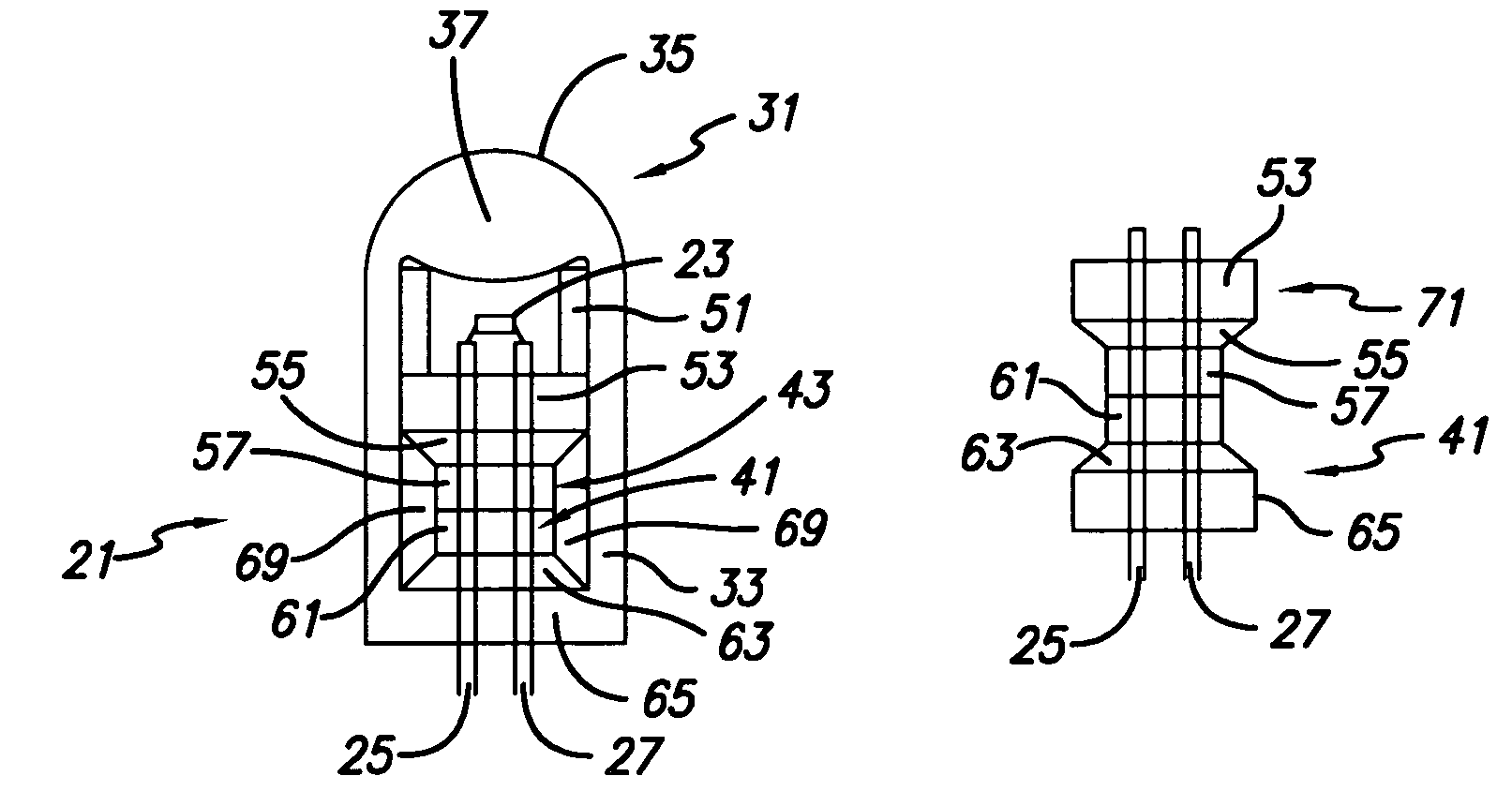
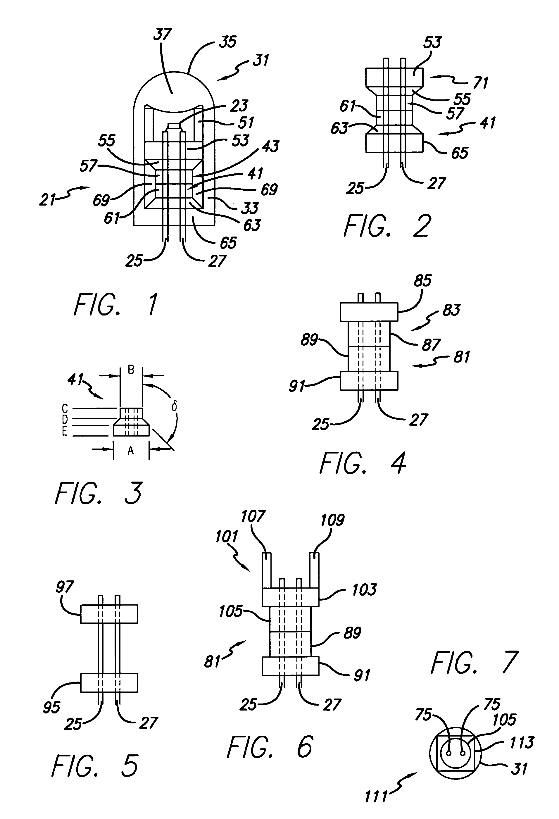
[0021]FIG. 1 is a plan view of a small incandescent lamp 21 of a well known construction, typically used for high intensity lamp applications. The lamp 21 includes a filament 23 that is attached at either of its ends to filament support legs 25 and 27 which are spaced apart conductors, typically 0.010 Dumet wire for small lamp applications. A glass envelope 31 has generally cylindrical side walls 33 and an end portion 35. End portion 35 has an optionally internally thickened portion 37 acting as a lens 37.

[0022]Internal structures in and around the filament support legs 25 and 27 and filament 23 may be seen as separate or as blended into the surrounding glass envelope 31 or into each other depending upon the level of processing. Some dividing lines are shown for purposes of discussion and to emphasize starting materials, but any combination of materials, once processed may lose their separate nature.

[0023]A lower bead structure 41 is shown having a line of separation with respect to...


PUM


Abstract

A shaped bead structure provides a bottom sealing periphery adjacent a non-bonding portion which may include an upper portion which may provide upper envelope stability and may but will preferably not bond to the glass envelope. The provision of a section of the glass envelope free of bonding above the lower peripheral sealing provides a leveraged stability to the upper portion of the glass envelope, and provides an annular space to prevent vertical spreading of a wetted glass envelope sealing zone with respect to a significant length of the glass envelope leaving it in tact and enabling it to “break” any vertically extending wetted interface and thus disrupt distortion forces. The use of two or more structures to provide a significant annular area of non-contact with the annular envelope can help to provide a structure which is not complex and easy to manufacture. Where two of the bead sections are stacked with the portions which are displaced significantly peripherally inwardly adjacent each other, an annular space is formed.

Description

FIELD OF THE INVENTION[0001]The present invention relates to the field of high intensity, efficient incandescent lamps especially small bulbs in which an improved geometry spacer bead is employed to limit contact with the envelope to automatically improve the precision during the sealing phase of bulb manufacture.BACKGROUND OF THE INVENTION[0002]Achievement of quality control in small incandescent lamps is a goal of long standing. The small size of the envelope, the leads the filament, makes the assembly subject to forces on sealing that are out of proportion to the structural integrity resulting from the small size of the components.[0003]In one well-known technique for constructing flashlight bulbs, a pressed and sintered glass bead was used in U.S. Pat. No. 4,618,799 which is incorporated herein by reference. The glass beads were tablet shaped with an outer periphery which was in close proximity to the inside of the glass envelope. Upon sealing, and especially in the usual case w...

Claims


Application Information

Patent Timeline
Patent Type & Authority Patents(United States)
IPC IPC(8): H01J17/18
CPCH01K1/18H01K1/22H01K1/30H01K1/38H01K3/12
Inventor CARLEY, JAMES A.
Owner CARLEY JAMES A
Why Eureka
Try Eureka