Heat-caulking device

a caulking device and heating technology, applied in the field of heat caulking devices, can solve the problems of difficult to evenly melt the whole of the boss, the joining strength of the first member and the second member is reduced, and achieves the effects of favorable melted and deformed, easy to operate, and intensive heating

Active Publication Date: 2021-04-15
HONDA MOTOR CO LTD
View PDF0 Cites 0 Cited by
  • Summary
  • Abstract
  • Description
  • Claims
  • Application Information

AI Technical Summary

Benefits of technology

[0013]As is clear from the above, this heat caulking device, by being provided with the connecting section as described above, makes it possible for heat to be generated substantially evenly in the whole of the heat chip having the substantially conical main body section. Hence, even using the heat chip having the substantially conical main body section in order that the first member and the second member are easily joined, the whole of the boss can be favorably melted and deformed, so the first member and the second member can be highly strongly joined.
[0014]In the above-described heat caulking device, it is preferable that the outer peripheral surface of the main body section is provided with a projection that projects toward a vicinity of the hole of the inner peripheral surface of the first member. In this case, as described above, heat can be generated substantially evenly in the whole of the heat chip due to the connecting section, and the boss can be intensively heated due to the projection. This makes it possible for the whole of the boss to be even more favorably melted and deformed, and for the first member and the second member to thereby be easily and highly strongly joined.
[0015]In the above-described heat caulking device, it is preferable that the projection has a projecting strip shape extending along a space between the one end surface side and the other end surface side of the main body section, and that an intersection point of the edge section on the one end surface side of the main body section and the connecting section is provided in a vicinity of an end section on the one end surface side of the projection. When the heat chip has been electrified, a resistance value gets smaller in the projection proportionately to the thickness being larger there compared to in another region of the heat chip, so it is easy for the generated heat amount to be reduced. By disposition of the intersection point with respect to this projection being set as described above, it becomes possible for a current to be effectively supplied to the projection via the connecting section. Therefore, occurrence of a difference in generated heat amount between the projection and another region whose thickness is smaller than that of said projection can be suppressed, so that heat can be generated substantially evenly in the whole of the heat chip. This makes it possible for the whole of the boss to be favorably melted and deformed, and for the first member and the second member to thereby be more highly strongly joined.
[0016]In the above-described heat caulking device, it is preferable that a plurality of the holes are provided so as to be lined up at intervals in a circumferential direction, and that the projection projects toward a space between of the holes. In this case, a plurality of the bosses can each be effectively melted and deformed at one time, and moreover the whole of those plurality of bosses can each be effectively melted and deformed. Hence, even, for example, a joined article including a plurality of the second members can be efficiently obtained since the plurality of second members can be joined at one time to the first member. Moreover, in the case where, for example, one second member has been provided with a plurality of the bosses, joining strength can be even more favorably improved, without joining efficiency of the first member and the second member being lowered.
[0017]In the above-described heat caulking device, it is preferable that the hole extends in a spiral from a center side in a radial direction of the first member, and that the projection extends along an extending direction of the hole, along a space between said holes. Even in the case of a boss inserted in the hole in this way, the whole of said boss can be favorably melted and deformed due to the heat chip provided with the projection as described above, so a joined article excelling in joining strength can be efficiently obtained.
[0018]Due to the present invention, the whole of the boss can be favorably melted and deformed using the substantially conical heat chip, so the first member and the second member can be easily and highly strongly joined.

Problems solved by technology

As a result, a generated heat amount on the one end surface side of the heat chip becomes smaller compared to a generated heat amount on its other end surface side, so it gets difficult for the whole of the boss to be evenly melted, and there is consequently concern that joining strength of the first member and the second member lowers.

Method used


Image

  • Heat-caulking device
  • Heat-caulking device
  • Heat-caulking device

Examples


Embodiment Construction

[0030]A preferred embodiment of a heat caulking device according to the present invention will be presented and described in detail with reference to the accompanying drawings.

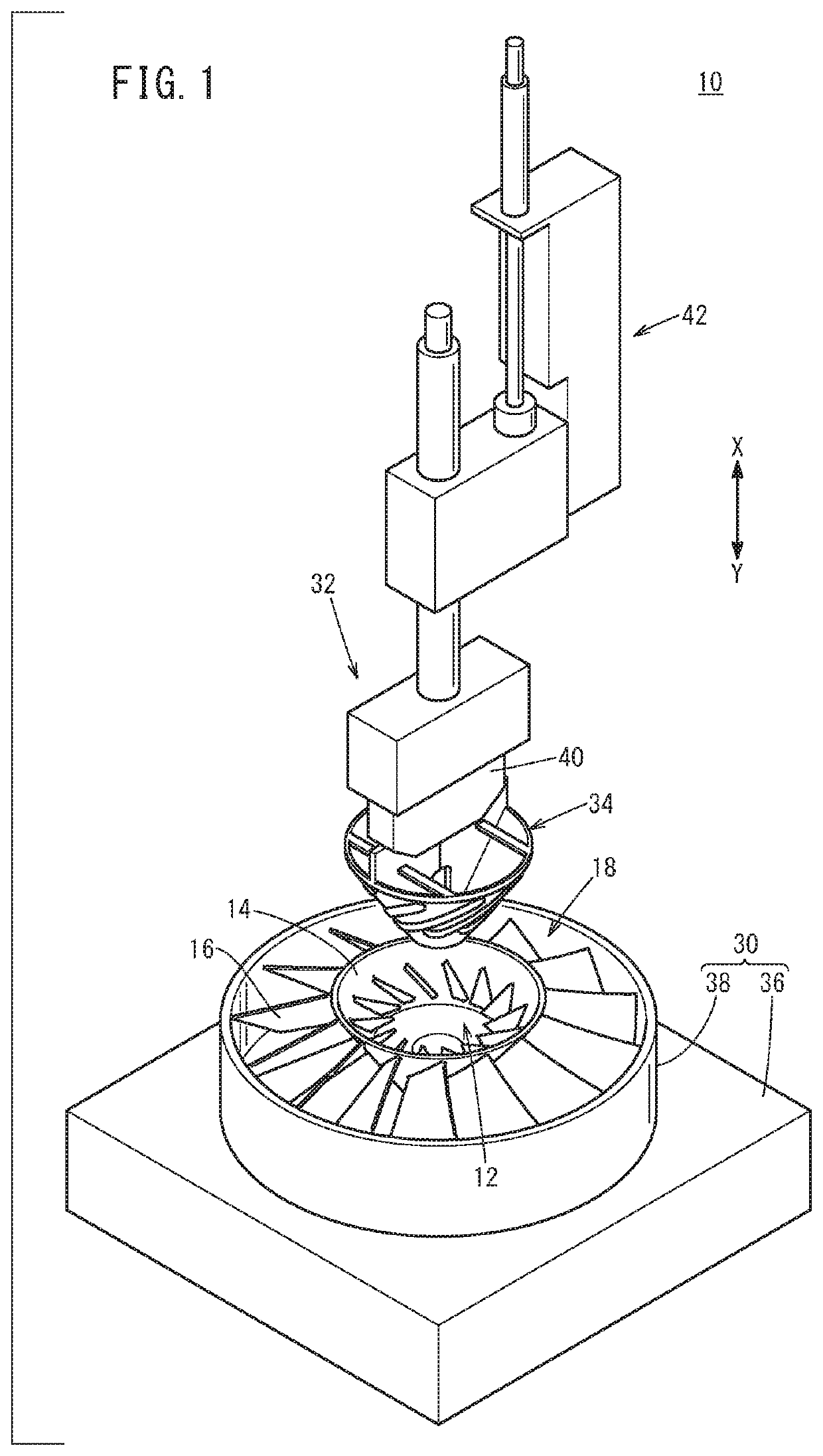
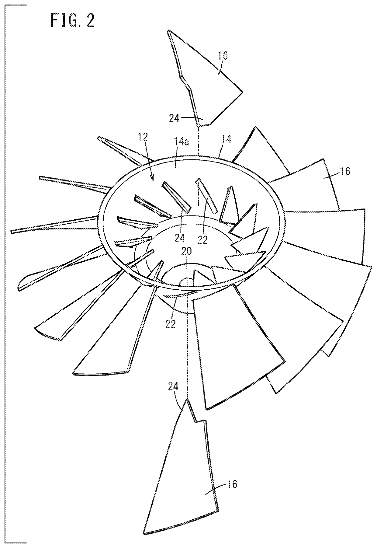
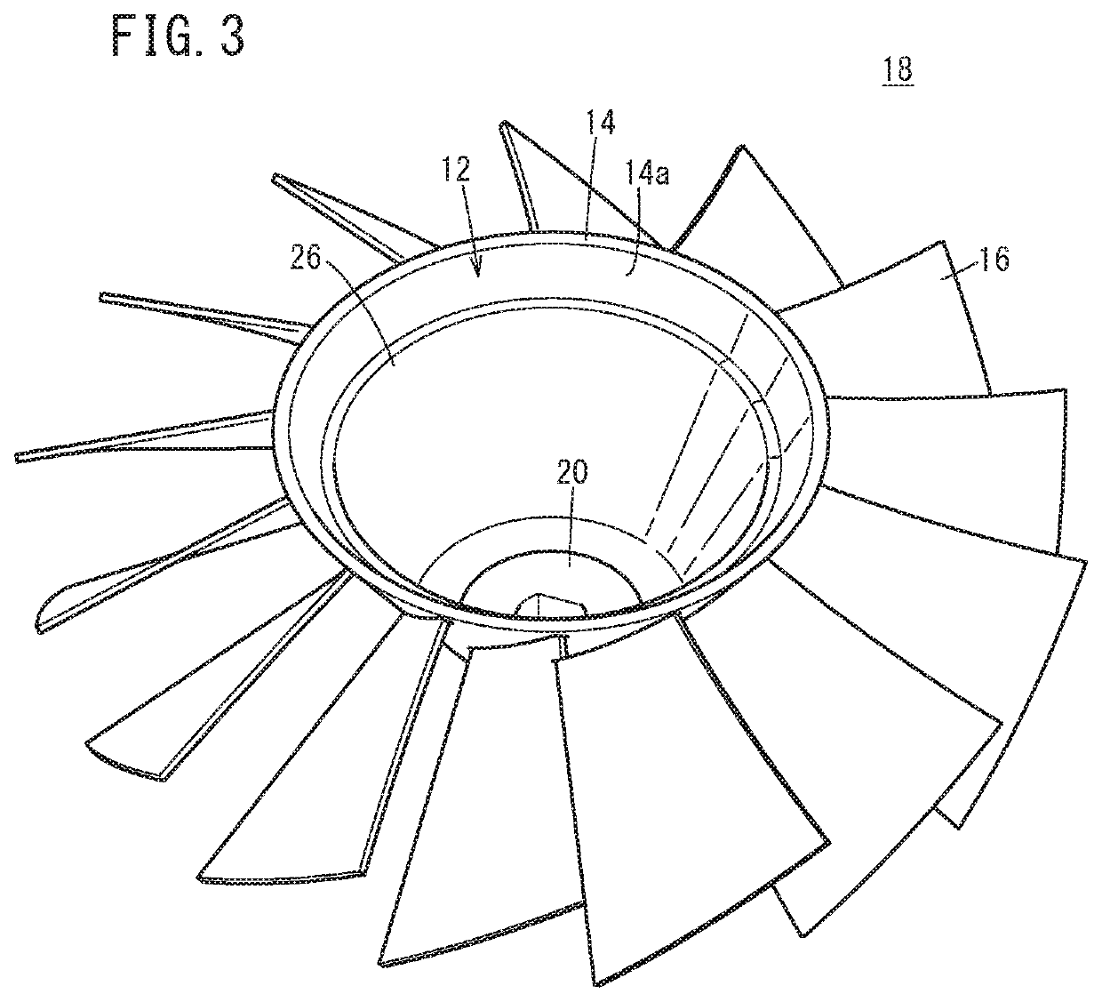
[0031]As shown in FIGS. 1-4, the present embodiment describes an example in which, by means of a heat caulking device 10 (refer to FIG. 1), a first member configured from a main plate 14 having a substantially conical (a substantially truncated cone shaped) hollow section 12 and a second member configured from a plurality of blades 16 are joined by heat caulking to obtain a joined body being an impeller 18 (refer to FIG. 3).

[0032]However, the joined body obtained by applying the heat caulking device 10 is not limited to the impeller 18. That is, the first member need only include the substantially conical hollow section 12, and other shapes or applications, and so on, are not specifically limited. Moreover, the second member need only include one or more bosses 24 that, by being inserted in one or more holes 2...


PUM

PropertyMeasurementUnit
lengthaaaaaaaaaa
currentaaaaaaaaaa
joining strengthaaaaaaaaaa

Abstract

This heat-caulking device is inserted into one or more holes penetrating a main plate having a substantially conical hollow portion, whereby one or more bosses of a blade protruding from an inner peripheral surface of the main plate toward the hollow portion are melted so as to join the main plate and the blade. A heat chip of the heat-caulking device has a substantially conical hollow main body portion, an outer peripheral surface of which conforms to the inner peripheral surface of the main plate. On the outer peripheral surface of the main body portion, a convex portion protruding toward the vicinity of the holes of the inner peripheral surface of the main plate is provided.

Description

TECHNICAL FIELD[0001]The present invention relates to a heat caulking device for joining a first member and a second member in such a manner that a boss of the second member that has been inserted in a hole of the first member is melted to join the first member and the second member.BACKGROUND ART[0002]As disclosed in, for example, Japanese Laid-Open Patent Publication No. 2007-307812, there is known a heat caulking device for joining a first member and a second member in such a manner that a boss of the second member that has been inserted in a hole of the first member is pressed on by a heat chip that has generated heat due to electrification, whereby the melted boss is expanded and deformed to join the first member and the second member.SUMMARY OF INVENTION[0003]In this kind of heat caulking device, it is conceivable that in the case where, for example, a first member having a substantially conical hollow section and a second member having a boss that projects from an inner perip...

Claims


Application Information

Patent Timeline
Patent Type & Authority Applications(United States)
IPC IPC(8): B29C65/22B29C65/30B29C65/00
CPCB29C65/226B29C65/224B29C66/612B29C66/73921B29C65/30B29C65/18B29C65/228B29C65/606B29C66/532B29C66/543B29C66/71B29C66/81415B29C66/81427B29C66/8322B29C66/843B29L2031/08B29K2023/12
Inventor ISHIKAWA, HIROSHITSURUGAI, YOSHINORITAJIRI, YUICHIAKAHORI, SHIGETOOHTSU, NAOHIROSHIOZAKI, SATOSHIURUSHIDANI, SHINZO
Owner HONDA MOTOR CO LTD
Why Eureka
Try Eureka