Reflective photomask blank and reflective photomask

Active Publication Date: 2020-07-09
TOPPAN PHOTOMASK CO LTD
View PDF0 Cites 0 Cited by
  • Summary
  • Abstract
  • Description
  • Claims
  • Application Information

AI Technical Summary

Benefits of technology

[0013]According to the present invention, it can be expected that the shadowing effect of a reflective photomask for pattern transfer using extreme ultraviolet light as a light sour

Problems solved by technology

Therefore, in the EUV lithography, it is not possible to use a refractive optical system that makes use of the transmission of light, and it is also not possible to use a transmissive photomask.
Further, as a component constituting an optical system of an exposure a

Method used


Image

  • Reflective photomask blank and reflective photomask
  • Reflective photomask blank and reflective photomask
  • Reflective photomask blank and reflective photomask

Examples


Example

EXAMPLE

[0078]Hereinafter, an Example of the present invention will be described.

[0079](Production of Reflective Photomask Blank)

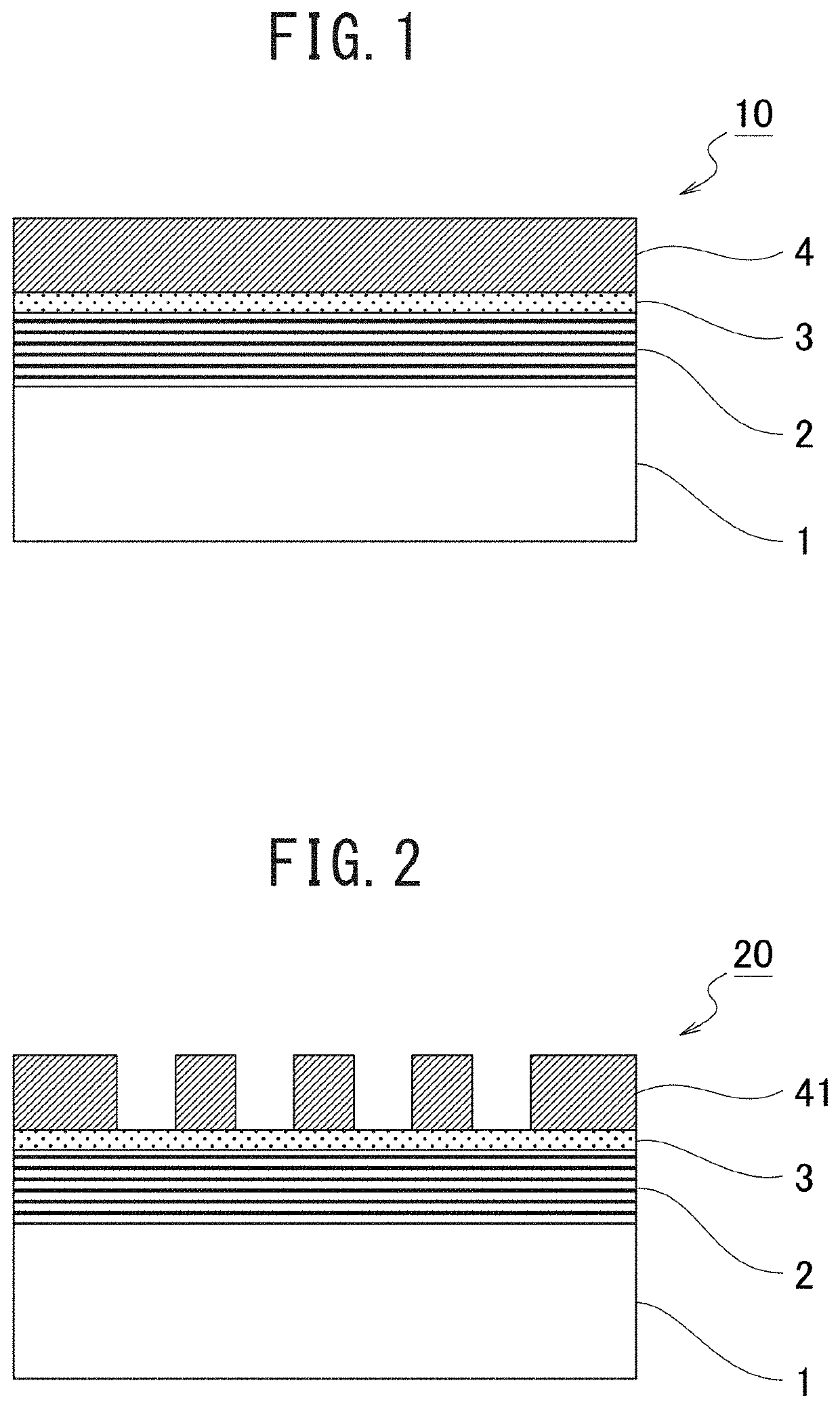
[0080]As a reflective photomask blank 100 with a layer structure illustrated in FIG. 10, a plurality of samples was produced in the following manner.

[0081]First, a reflective layer 12 of a multilayer structure composed of 40 pairs of Si and Mo (total film thickness 280 nm) was formed on a substrate 11 made of synthetic quartz, and a capping layer 13 composed of a Ru film was formed to a film thickness of 2.5 nm on the reflective layer 12. Then, a light absorbing layer 14 was formed on the capping layer 13. Then, a conductive layer 15 made of CrN was formed to a film thickness of 100 nm on a back surface of the substrate 11.

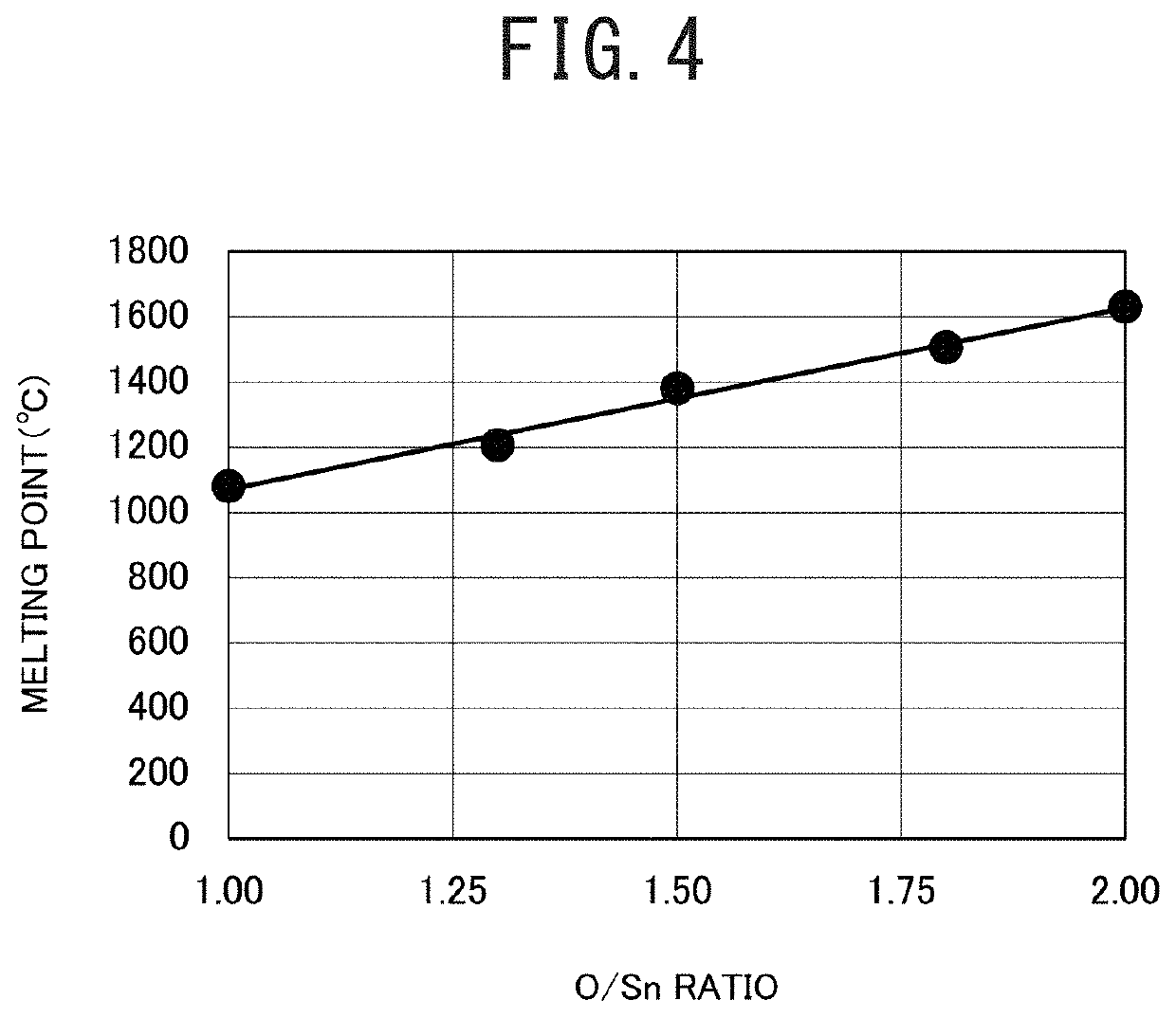
[0082]The light absorbing layer 14 was formed in each of the samples by changing the material (Ta or tin oxide) and the film thickness as indicated in Table 1. As the tin oxide films, SnO films with an O / Sn ratio of 1 (indicated as “SnO1”...


PUM


Abstract

A reflective photomask blank (10) of a first aspect includes a substrate (1); a reflective layer (2) formed on the substrate (1); and a light absorbing layer (4) formed on the reflective layer (2) and including a tin oxide film with a film thickness of 17 nm or more and less than 25.0 nm. Consequently, the shadowing effect of a reflective photomask for pattern transfer using extreme ultraviolet light as a light source is suppressed or reduced to improve the performance of transfer to a semiconductor substrate, and further, pattern collapse due to cleaning of the reflective photomask is suppressed.

Description

TECHNICAL FIELD[0001]The present invention relates to a reflective photomask for use in lithography that uses extreme ultraviolet light as a light source, and to a reflective photomask blank for use in producing the reflective photomask.BACKGROUND ART[0002]With the miniaturization of semiconductor devices, the demand for the miniaturization of the photolithography technology has been increasing in the semiconductor device manufacturing process. The minimum resolution size of a transfer pattern in the photolithography largely depends on the wavelength of an exposure light source and can be reduced as the wavelength decreases. Therefore, in order to realize further miniaturization of transfer patterns, exposure light sources are shifting from conventional ArF excimer lasers (wavelength 193 nm) to EUV (Extreme Ultra Violet) with a wavelength of 13.5 nm.[0003]The EUV is absorbed by most materials at high rates. Therefore, in the EUV lithography, it is not possible to use a refractive op...

Claims


Application Information

Patent Timeline
IPC IPC(8): G03F1/24G03F1/58
CPCG03F1/58G03F1/24G03F1/54G03F1/52
Inventor KOMIZO, TORUFUKUGAMI, NORIHITO
Owner TOPPAN PHOTOMASK CO LTD
Why Eureka
Try Eureka