Method and device for efficient communication in next generation mobile communication system

Active Publication Date: 2020-07-16
SAMSUNG ELECTRONICS CO LTD
View PDF0 Cites 17 Cited by
  • Summary
  • Abstract
  • Description
  • Claims
  • Application Information

AI Technical Summary

Benefits of technology

[0018]According to an embodiment of the disclosure, it is possible to reduce data transmission overhead and efficiently use radio resources by proposing an efficient RLC UM segmentation operation in a next-generation mobile communication system, thereby minimizing un

Problems solved by technology

Accordingly, if the terminal constantly receives and identifies a

Method used


Image

  • Method and device for efficient communication in next generation mobile communication system
  • Method and device for efficient communication in next generation mobile communication system
  • Method and device for efficient communication in next generation mobile communication system

Examples


embodiment 1

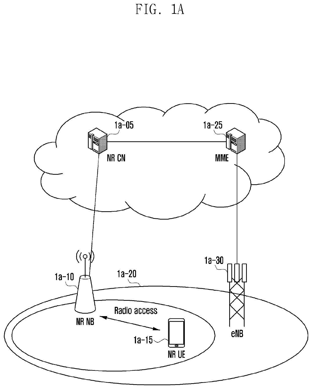
[0063]FIG. 1A illustrates the structure of a next-generation mobile communication system according to an embodiment of the disclosure.

[0064]Referring to FIG. 1A, a radio access network of the next-generation mobile communication system includes a next-generation base station 1a-10 (hereinafter, referred to as a new radio node B (NR NB) or a base station) and a new radio core network (NR CN) 1a-05, as illustrated in FIG. 1A. A user terminal 1a-15 (hereinafter, referred to as a new radio user equipment (NR UE) or a terminal) accesses an external network through the NR NB 1a-10 and the NR CN 1a-05.

[0065]In FIG. 1A, the NR NB 1a-10 corresponds to an evolved Node B (eNB) in a conventional UE system. The NR NB 1a-10 may be connected to the NR LTE 1a-15 and may provide better service than a conventional node B. Since all user traffic is served through a shared channel in the next-generation mobile communication system, a device for collecting and scheduling status information of buffer sta...

embodiment 2

[0155]FIG. 2A illustrates the structure of a next-generation mobile communication system according to an embodiment of the disclosure.

[0156]Referring to FIG. 2A, a radio access network of the next-generation mobile communication system includes a next-generation base station 2a-10 (hereinafter, referred to as a new radio node B (NR NB) or a base station) and a new radio core network (NR. CN) 2a-05 as illustrated in FIG. 2A. A user terminal 2a-15 (hereinafter, referred to as a new radio user equipment (NR UE) or a terminal) accesses an external network through the NR NB 2a-10 and the NR CN 2a-05.

[0157]In FIG. 2A, the NR NB 2a-10 corresponds to an evolved Node B (eNB) of the conventional LTE system. The NR NB 2a-10 may be connected to the NR LTE 2a-15 and may provide better service than a conventional node B. Since all user traffic is served through a shared channel in the next-generation mobile communication system, a device for collecting and scheduling status information of buffer ...

embodiment 3

[0252]FIG. 3A illustrates the structure of an UE system according to an embodiment of the disclosure.

[0253]Referring to FIG. 3A, a radio access network of the LTE system includes next-generation base stations 3a-05, 3a-10, 3a-15, and 3a-20 (hereinafter, referred to as evolved node Bs (ENBs), Node Bs, or base stations), a mobility management entity (MIME) 3a-25, and a serving gateway (S-GW) 3a-30 as illustrated in FIG. 3A. A User Equipment 3a-35 (hereinafter, referred to as a UE or a terminal) accesses an external network through the ENBs 3a-05, 3a-10, 3a-15, and 3a-20 and the S-GW 3a-30.

[0254]In FIG. 3A, the ENBs 3a-05, 3a-10, 3a-15, and 3a-20 correspond to the existing node Bs of the UMTS system. The ENB 3a-05 is connected to the UE 3a-35 through a radio channel, and performs a more complicated role than a conventional node B. In the LTE system, since all user traffic including a real-time service such as a VoIP (Voice over IP) through an Internet protocol is served through a share...


PUM


Abstract

The present disclosure relates to a communication technique for convergence of a 5G communication system for supporting a higher data transmission rate beyond a 4G system with an IoT technology, and a system therefor. The present disclosure may be applied to an intelligent service (for example, smart home, smart building, smart city, smart car or connected car, health care, digital education, retail business, security and safety-related service, etc.) on the basis of a 5G communication technology and an IoT-related technology. The present disclosure relates to a method of a terminal, the method comprising the steps of: determining a path loss reference beam on the basis of whether information indicating the path loss reference beam is received; obtaining a path loss on the basis of the path loss reference beam; obtaining a power headroom (PH) on the basis of the path loss; and transmitting a power headroom report (PHR) including the PH.

Description

CROSS-REFERENCE TO RELATED APPLICATIONS[0001]This application is a 371 National Stage of International Application No. PCT / KR2018 / 006099, filed May 29, 2018, which claims priority to Korean Patent Application No. 10-2017-0090934, filed Jul. 18, 2017, the disclosures of which are herein incorporated by reference in their entirety.BACKGROUND1. Field[0002]The disclosure relates to the operation of a terminal and a base station in a mobile communication system. The disclosure relates to a random-access method in a next-generation mobile communication system. The disclosure relates to determination of transmission power and a power headroom report (PHR) in a next-generation mobile communication system. The disclosure relates to a method and an apparatus for efficiently splitting data in a next-generation mobile communication system. Further, the disclosure relates to a method and an apparatus by which a radio resource control (RRC)-inactive mode terminal transmits data in a next-generati...

Claims


Application Information

Patent Timeline
IPC IPC(8): H04W52/36H04W52/24H04W76/27H04W28/06H04W74/08H04W72/14H04W74/00
CPCH04W74/006H04W72/14H04W76/27H04W52/365H04W28/06H04W74/0833H04W52/242H04W76/20H04W52/146H04W52/42H04B7/0408H04B7/0695H04B17/309H04W72/23
Inventor KIM, DONGGUNKIM, SOENGHUNSAYENKO, ALEXANDERKIM, SANGBUMJANG, JAEHYUK
Owner SAMSUNG ELECTRONICS CO LTD
Why Eureka
Try Eureka