Method For Assembling An Aircraft Pylon

a technology of aircraft pylons and pylons, which is applied in the direction of aircraft power plants, power plant construction, power plant types, etc., can solve the problems of long installation and complex system for operators, and achieve the effect of easy installation, improved visibility for operators, and internal system

Inactive Publication Date: 2020-07-23
AIRBUS OPERATIONS (SAS) +1
View PDF0 Cites 1 Cited by
  • Summary
  • Abstract
  • Description
  • Claims
  • Application Information

AI Technical Summary

Benefits of technology

[0021]According to an aspect of the invention, the internal systems are installed more easily, wit...

Problems solved by technology

According to this operating mode, accessibility for installing the systems within the already-assembled primar...

Method used


Image

  • Method For Assembling An Aircraft Pylon
  • Method For Assembling An Aircraft Pylon
  • Method For Assembling An Aircraft Pylon

Examples


Embodiment Construction

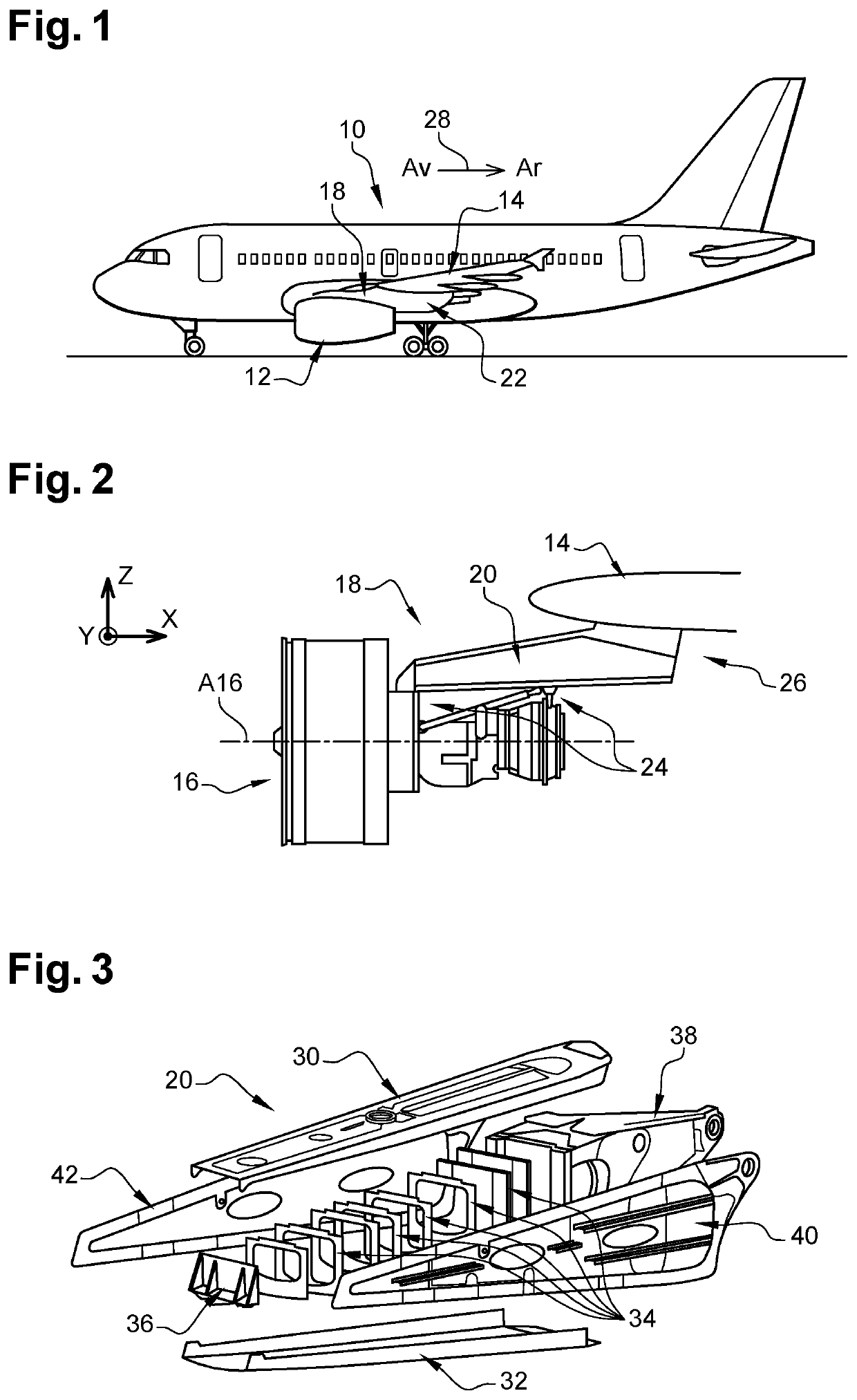
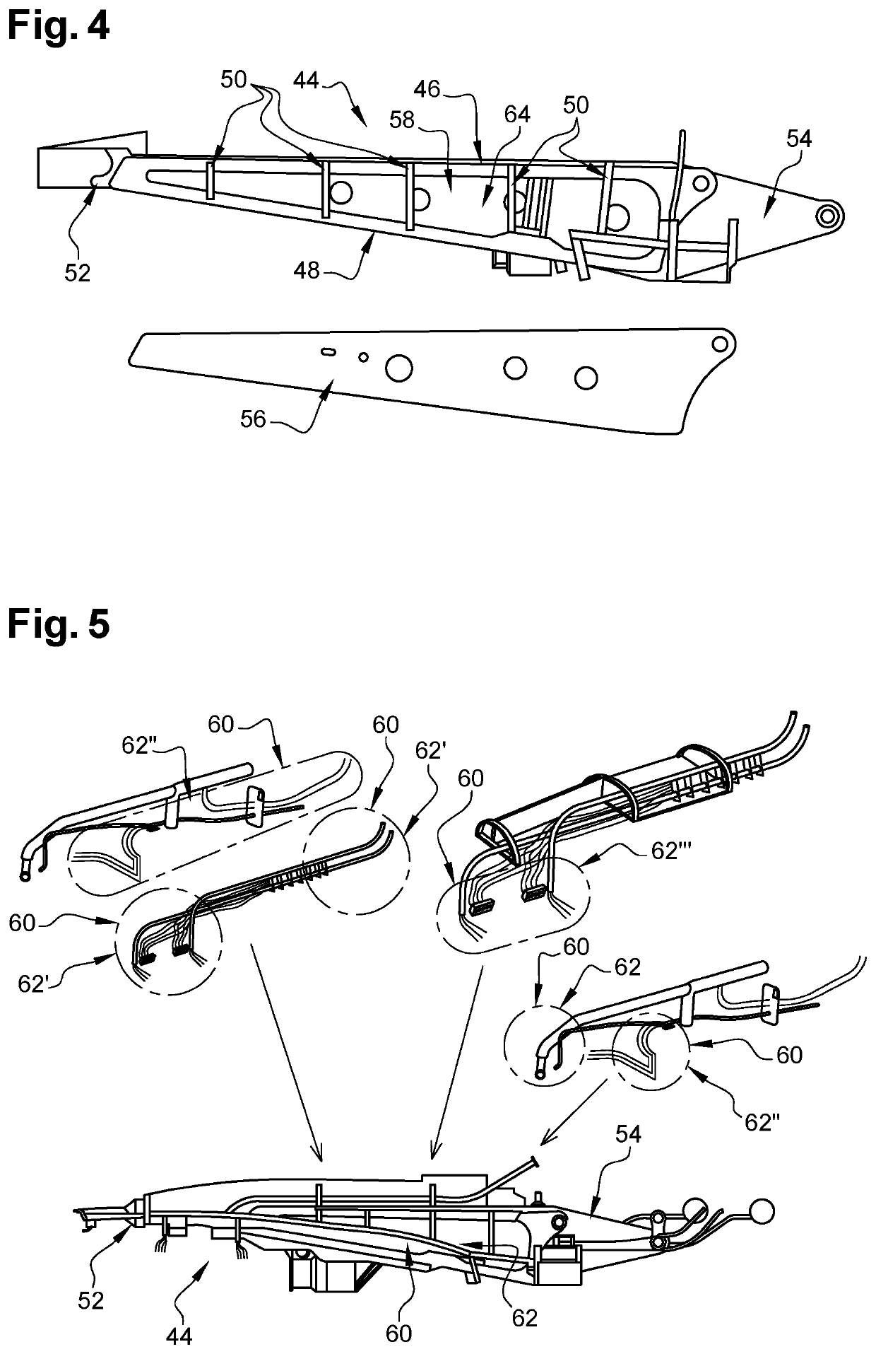
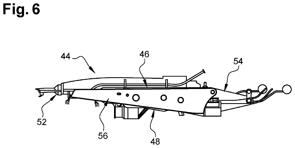
[0030]FIGS. 4 to 6 show a primary structure 44 of an aircraft pylon which comprises:[0031]an upper spar 46,[0032]a lower spar 48,[0033]transverse frames 50 which connect the upper and lower spars 46, 48, which are arranged in transverse planes and which each have an approximately square or rectangular contour,[0034]a front end wall 52 which connects a front end of the upper spar 46 and a front end of the lower spar 48,[0035]a rear end part 54 which connects a rear end of the upper spar 46 and a rear end of the lower spar 48,[0036]two lateral panels 56, 58 arranged on either side of the transverse frames 50.

[0037]According to one embodiment, the primary structure 44 comprises upper and lower spars 46, 48, transverse frames 50 connecting the upper and lower spars 46, 48 and first and second lateral panels 56, 58 that are arranged on either side of the transverse frames 50.

[0038]The aircraft pylon also comprises at least one internal system 60 positioned at least partially within the p...


PUM


Abstract

A method for assembling an aircraft pylon having a primary structure and at least one internal system at least partially positioned within the primary structure, wherein the internal system is positioned inside the primary structure before the last lateral panel of the primary structure is attached. The absence of one of the lateral panels facilitates the installation of the internal systems.

Description

FIELD OF THE INVENTION[0001]The present application relates to a method for assembling an aircraft pylon.BACKGROUND OF THE INVENTION[0002]According to a configuration shown in FIGS. 1 and 2, an aircraft 10 comprises multiple propulsion units 12 positioned below the wing 14 of the aircraft 10.[0003]A propulsion unit 12 comprises an engine 16, a nacelle (not shown in FIG. 2) positioned around the engine 16, and a pylon 18 that provides the connection between the engine 16 and the wing 14. The pylon 18 comprises a rigid primary structure 20 which, among other things, serves to transmit forces between the engine 16 and the rest of the aircraft 10, a secondary structure 22 which encloses the primary structure 20 and reduces the drag of the pylon 18, and systems located inside and outside the primary structure 20. According to one configuration, the primary structure 20 is connected to the engine 16 by an engine attachment 24 and to the wing 14 by a wing attachment 26.[0004]For the presen...

Claims


Application Information

Patent Timeline
IPC IPC(8): B64D27/26B64D27/18
CPCB64D2027/262B64D27/26B64D27/18B64C3/182B64C3/32B64D2027/266B64F5/10B64D2027/264
Inventor MARTINEL, FRANÇOISDEDIEU, JOELTHERON, THIERRYMOULIS, JULIENDEFORET, THOMASBENABEN, AUDREYWHIFFEN, ROBERT
Owner AIRBUS OPERATIONS (SAS)
Why Eureka
Try Eureka