Display device and control circuit
a control circuit and display device technology, applied in the direction of instruments, computing, electric digital data processing, etc., can solve the problem of difficulty in ensuring a sufficient touch period
- Summary
- Abstract
- Description
- Claims
- Application Information
AI Technical Summary
Benefits of technology
Problems solved by technology
Method used
Image


Examples
embodiment
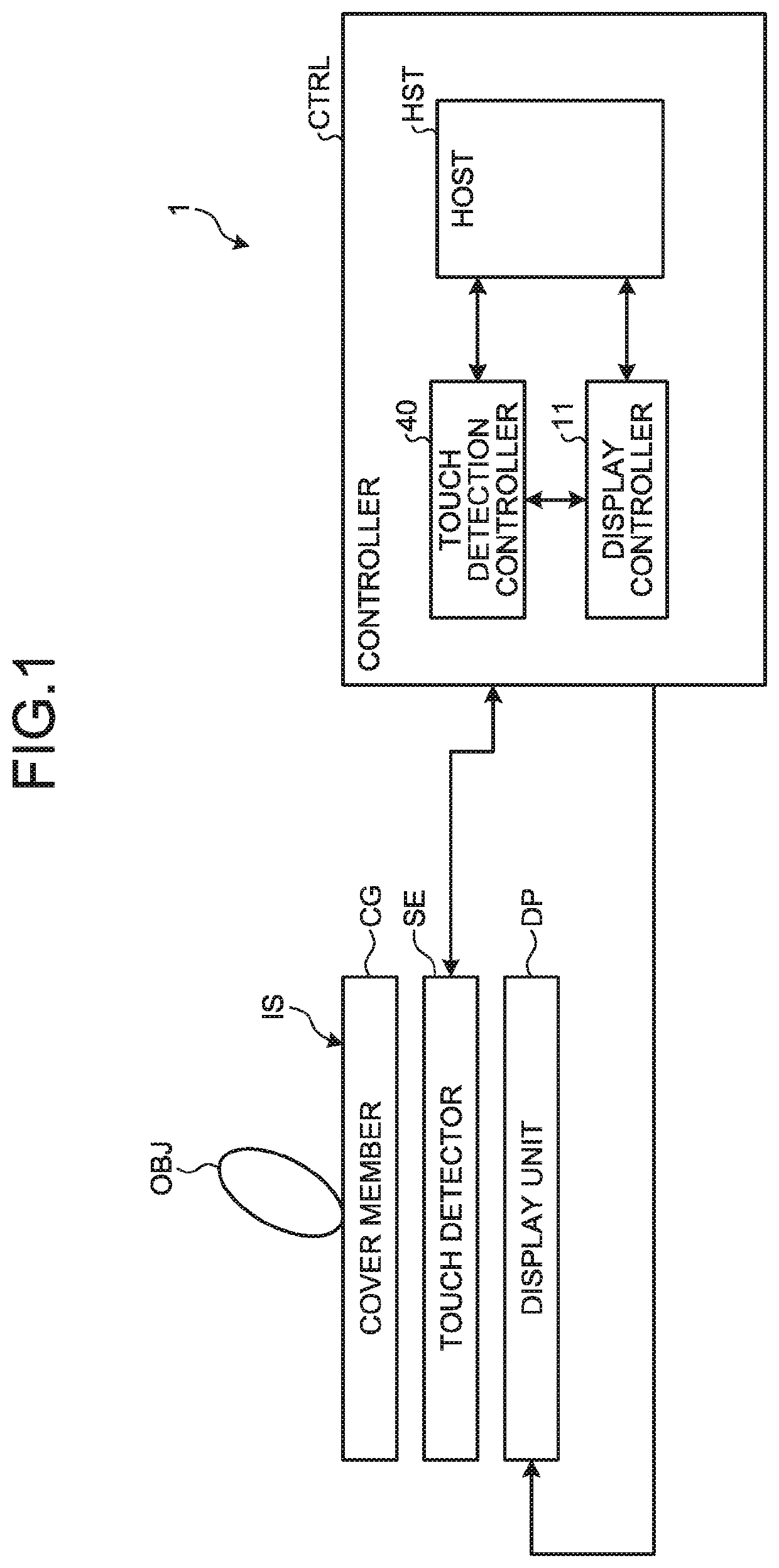
[0061]FIG. 1 is a block diagram illustrating a configuration of a display device with a touch detection function according to an embodiment.
[0062]A display device 1 with a touch detection function (hereinafter referred to as the display device 1) according to the present embodiment includes a touch detector SE, a display unit DP, and a controller CTRL.
[0063]The touch detector SE detects contact or proximity of an object OBJ with or to an input surface IS of a cover member CG. Specifically, the touch detector SE outputs to the controller CTRL a signal value according to contact or proximity of the object OBJ with or to a region in which the object OBJ overlaps the input surface IS in the vertical direction.
[0064]The object OBJ may be a first type object that deforms by coming into contact with the input surface IS, or may be a second type object that does not deform by coming into contact with the input surface IS or that is relatively less deformable in comparison with the first typ...
first embodiment
[0188]FIG. 16 is a diagram illustrating a configuration example of a display controller of a display device according to a first embodiment. As illustrated in FIG. 16, the display controller 11 of the display device 1 in the first embodiment includes a drive controller 111 and a control switching unit 112. The basic operation of the display controller 11 is as discussed above. The following describes the operations of the drive controller 111 and the control switching unit 112 in switching a display resolution and changing a ratio between the display period Pd and the touch periods Ptm, Pts1, and Pts2 in one frame period, in accordance with the video signals Vdisp. The following describes the switching operation between the display period Pd in which a display operation is performed and the touch period Ptm in which a mutual-capacitance touch detection operation is performed in the seventeen periods from the period T4 to the period T20 illustrated in FIG. 14.
[0189]The drive controll...
second embodiment
[0261]FIG. 34 is a diagram illustrating an example of a timing chart when a display device according to a second embodiment performs the image display at a low resolution. The second embodiment is the same as the first embodiment in the configuration of the display device 1, the operation example in the display period during the image display at the maximum resolution, the operation example in the display period during the image display at a low resolution, the operation example in the touch period, the timing chart when the image display is performed at the maximum resolution, and others, and thus the redundant description is omitted.
[0262]The example illustrated in FIG. 34 indicates the scanning signals Vscan(1), Vscan(2), Vscan(88) output to the respective eighty eight gate lines GCL, the display drive voltage Vcomd applied to the drive electrodes COML, and the touch drive signal Vcomtm. In the example illustrated in FIG. 34, the display drive voltage Vcomd and the touch drive si...
PUM
 Abstract
Description
Claims
Application Information
 - Generate Ideas
- Intellectual Property
- Life Sciences
- Materials
- Tech Scout
- Unparalleled Data Quality
- Higher Quality Content
- 60% Fewer Hallucinations
Browse by: Latest US Patents, China's latest patents, Technical Efficacy Thesaurus, Application Domain, Technology Topic, Popular Technical Reports.
© 2025 PatSnap. All rights reserved.Legal|Privacy policy|Modern Slavery Act Transparency Statement|Sitemap|About US| Contact US: help@patsnap.com