Infrared device

a technology of infrared device and infrared source, which is applied in the direction of ohmic-resistance heating device, microstructural device, microstructure technology, etc., can solve the problems of limited infrared source operation temperature, limited efficiency of infrared source, and still unsatisfactory arrangemen

Active Publication Date: 2020-07-23
COMMISSARIAT A LENERGIE ATOMIQUE ET AUX ENERGIES ALTERNATIVES
View PDF7 Cites 0 Cited by
  • Summary
  • Abstract
  • Description
  • Claims
  • Application Information

AI Technical Summary

Benefits of technology

[0017]at least one resistive element for emitting an infrared radiation when a current flows therethrough, said at least one resistive element being held in suspension, by at least two suspension arms, in the cavity, said suspension arms being arranged to make an electrical contact between the resistive element and two connection terminals disposed outside the cavity,

Problems solved by technology

This operating temperature of the infrared source however remains limited, and cannot exceed the degradation temperature of the constituent elements of the infrared source, de facto restraining the intensity of the infrared radiation likely to be emitted by said source.
The efficiency of the infrared source is also limited by air conduction losses which can occur when the latter is operating.
However, such an arrangement is still not satisfactory.
Indeed, the radiation emitted by the infrared source remains highly dispersed, such that only a relevant fraction of said radiation is efficiently used for gas detection.

Method used


Image

  • Infrared device
  • Infrared device
  • Infrared device

Examples


first embodiment

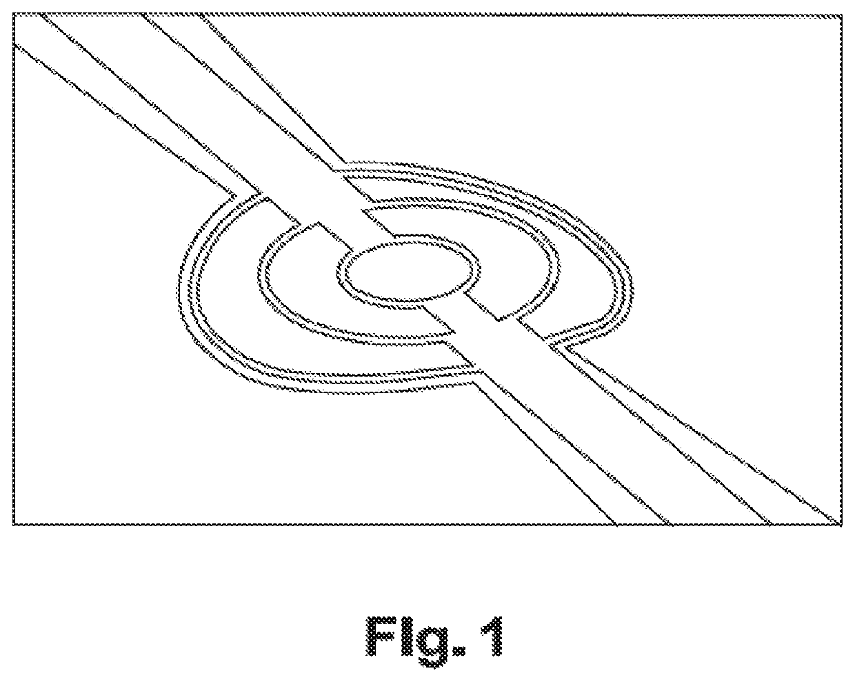
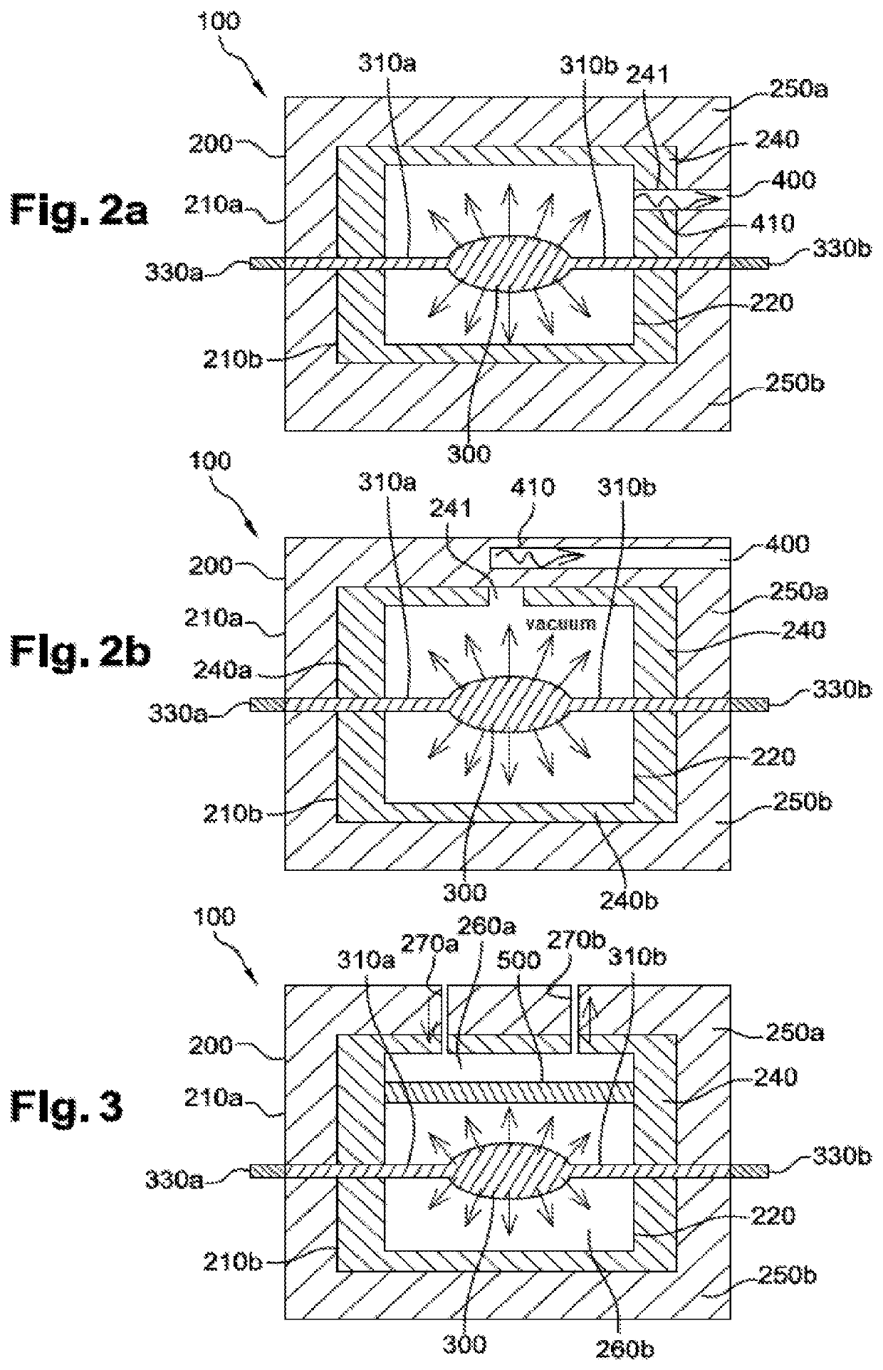
[0084] the infrared device can comprise a waveguide 400.

[0085]By “waveguide”, it is meant a channel adapted to guide a light radiation in the extension direction of said channel.

[0086]Moreover, according to this embodiment, the reflective coating 240 comprises a through opening 241, and is arranged such that only the infrared radiation, likely to be emitted by the resistive element 300, and passing through the through opening 241 diffuses out of the cavity 220.

[0087]The waveguide 400, for the purposes of the present invention, is thereby coupled along its first end 410 to the cavity 220 at the through opening 241, such that an infrared radiation diffusing out of the cavity is at least partly guided by the waveguide.

[0088]It is clear, without needing to specify it, that the waveguide is disposed out of the cavity.

[0089]Advantageously, the waveguide can comprise a core made of an SiGe alloy.

[0090]According to a first alternative of the first embodiment illustrated in FIG. 2a, the firs...

second embodiment

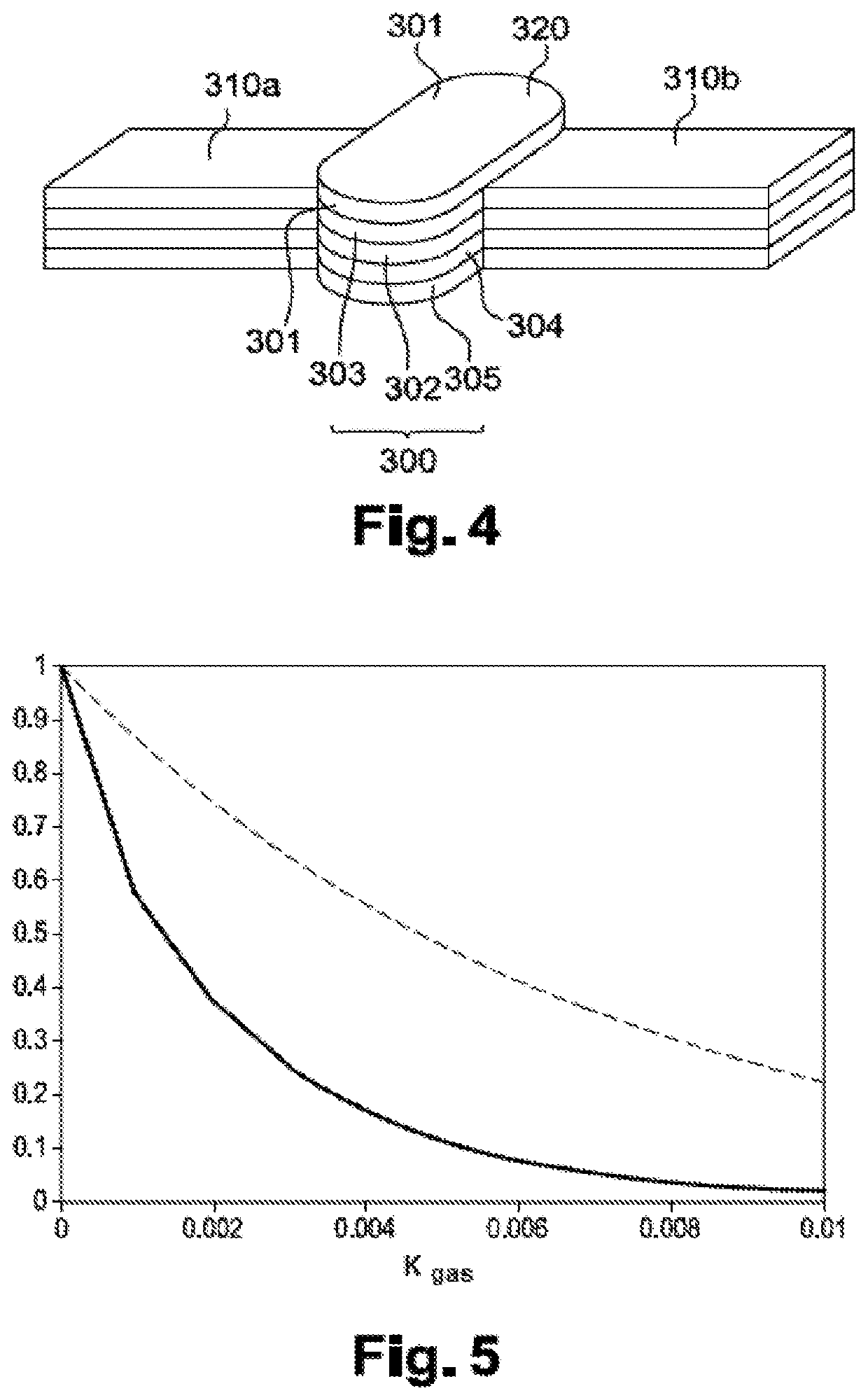
[0122]The implementation of the reflective coating for the purposes of the present invention enables multiple reflections for the infrared radiation to be considered, and thus the probability of absorbing said infrared radiation by the gas to be increased. The temperature variations thus observed at the resistive element 300 are thereby intensified, such that the infrared device can make up a gas detector with an improved sensitivity with respect to the same detector without a reflective coating.

[0123]In particular, the temperature variations of the resistive element 300 can be detected via the measurement of the current flowing (for example with an amperemeter) in said resistive element as a function of the electric voltage imposed thereto.

[0124]The gas can thus be detected by an abrupt cooling of the resistive element 300.

[0125]By way of example, the inventors have determined by numerical simulation the reflective coating effect on the sensitivity of a gas detector according to t...


PUM

PropertyMeasurementUnit
reflectivity coefficientaaaaaaaaaa
pressureaaaaaaaaaa
reflectivity coefficientaaaaaaaaaa

Abstract

The invention relates to an infrared device comprising a resistive element suspended in a cavity formed in a main element, and capable of transmitting infrared radiation when it is fed with an electric current. In particular, the main element is at least partly covered on the outer surface thereof and/or the inner surface thereof with a reflective coating. The use of the reflective coating makes it possible to at least partly contain infrared radiation transmitted by the resistive element in the cavity.

Description

TECHNICAL FIELD[0001]The present invention relates to an infrared device provided with an infrared source. In particular, the present invention relates to an infrared device for detecting gas.PRIOR ART[0002]Non-dispersive infrared (“NDIR”) sources are known in the state of the art, and are commonly implemented in gas detectors.[0003]By way of example, FIG. 1 illustrates an infrared micro-source known in the state of the art and described by Barritault et al. [1]. In particular, the infrared micro-source comprises a metal filament formed on a membrane suspended by two suspension arms.[0004]The metal filament, when an electric current flows therethrough, heats and emits an infrared radiation according to the black body law.[0005]In other words, the intensity of the infrared radiation increases with the temperature at which the metal filament is heated.[0006]This operating temperature of the infrared source however remains limited, and cannot exceed the degradation temperature of the c...

Claims


Application Information

Patent Timeline
Patent Type & Authority Applications(United States)
IPC IPC(8): H01K1/32H01K1/08H01K1/10H01K3/26H05B3/00G01N21/3504G01J3/10
CPCH01K3/26G01J3/108H05B3/0033G01N21/3504H01K1/325G01N2201/06186H01K1/10H01K1/08B81B7/0067B81B2201/047B81C2203/0118B81C2203/035G01N21/3577H01K1/14H01K1/28H01K1/36H01K1/50H01K3/02H01K3/12H01K7/00
Inventor BOUTAMI, SALIMLORENT, EMERICK
Owner COMMISSARIAT A LENERGIE ATOMIQUE ET AUX ENERGIES ALTERNATIVES
Why Eureka
Try Eureka