
Screening apparatus

a screening apparatus and shale shaker technology, applied in the direction of screening, mechanical vibration separation, screening, etc., can solve the problems of relative heavyness, relative high basket, and bearing mounting eccentric weighted shaft wear

Inactive Publication Date: 2020-07-30
AXIOM PROCESS
View PDF0 Cites 1 Cited by
  • Summary
  • Abstract
  • Description
  • Claims
  • Application Information

AI Technical Summary

Benefits of technology

The patent is about a shale shmaker basket that has drive mechanisms to vibrate it. The basket is reinforced with ribs on its sides, which support a platform that mounts the drive mechanism. The ribs are angled downwards towards the back of the basket, to match the typical angle of vibration. This design helps to make the basket stronger and more durable. The drive mechanisms can be powered by electric or hydraulic motors, and the motor can be located on the same side of the basket as the drive mechanisms. This simplifies the design of the shake shaker.

Problems solved by technology

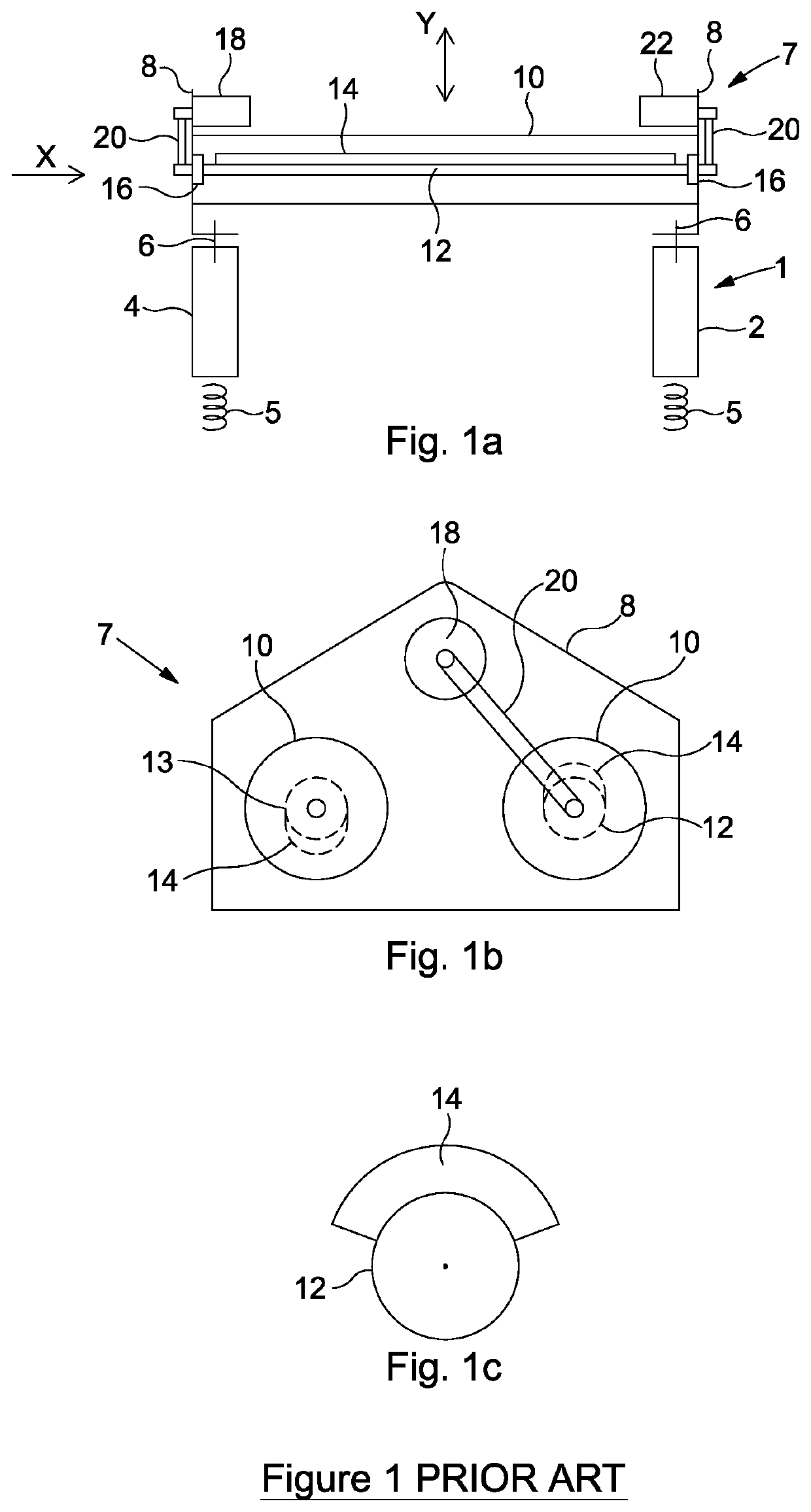
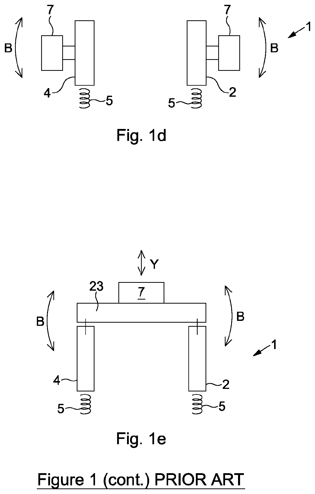
Arrangements such as those of FIGS. 1a to 1c can be effective, but they are relatively heavy and the bearings mounting the eccentrically weighted shafts are subject to wear due to flexing or bending forces.
The relatively bulky arrangement also tends to be mounted relatively high on the basket so as not to interfere with access to the screening surfaces, resulting in a relatively high basket.
This can be inconvenient where head height is limited.
This arrangement has the disadvantage of adding to the basket width and may apply significant bending forces to the basket sides.
Shale shakers are becoming more complex, being provided with multiple screen decks and having increased capability given by flow distributors and solids collection arrangements.

Method used


Image

  • Screening apparatus
  • Screening apparatus
  • Screening apparatus

Examples


Embodiment Construction

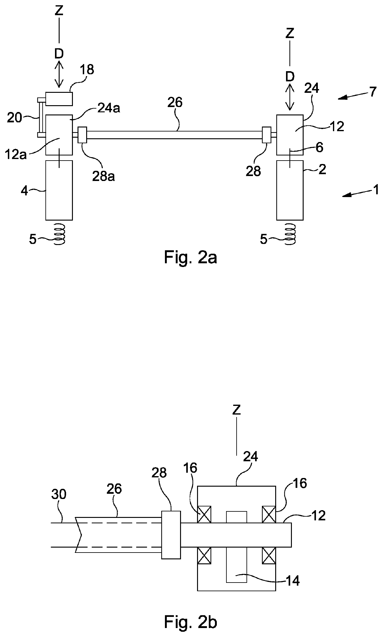
[0013]According to a first aspect the present invention provides a basket for a shale shaker, the basket comprising a front, solids discharge end and a rear, feed end spaced apart by opposed first and second sides;

wherein the first and second sides mount a drive mechanism comprising:

a) a first eccentrically weighted shaft, mounted to the first side of the basket for rotation about an axis transverse to the front to rear direction of the basket;

b) a first shaft drive, coupled to the first shaft and to;

c) a corresponding second eccentrically weighted shaft, mounted to the second side of the basket for rotation about an axis transverse to the front to rear direction of the basket.

[0014]Conveniently the first and second eccentrically weighted shafts may be mounted for rotation about a substantially horizontal axis transverse to the front to rear direction of the basket. It will be understood that there may be some deviation from exactly horizontal in such an arrangement, for example of ...


PUM


Abstract

A basket (1) for a shale shaker includes a front, solids discharge end (34) and a rear, feed end (36) spaced apart by opposed first and second sides (2,4). The first and second sides mount a drive mechanism (7). The drive mechanism includes a first eccentrically weighted shaft (12), mounted to the first side (2) of the basket for rotation about an axis transverse to the front to rear direction of the basket; a first shaft drive, coupled to the first shaft (12) and to a corresponding second eccentrically weighted shaft (12a), which is mounted to the second side of the basket (4) for rotation about an axis transverse to the front to rear direction of the basket. A drive module (48, 50) comprising two eccentrically weighted shafts mounted on bearings in a single housing (52) is also described.

Description

FIELD OF THE INVENTION[0001]The invention relates to shale shakers as used for example for separating drill cuttings from used drilling mud when drilling operations such as drilling an oil well are being carried out. In particular the invention relates to the vibratory drive mechanisms used to achieve solids and liquid separation in the basket of shale shaker machines.BACKGROUND TO THE INVENTION[0002]Shale shakers are vibratory screening machines that include a vibratory basket mounted on a base by means of resilient mounts such as springs or rubber blocks.[0003]The basket is typically generally cuboid in form. The basket has a solids discharge end, typically described as the front of the basket and a rear feed end typically described as the rear or the back of the basket. Two sides complete the generally cuboid shape.[0004]A screen deck or screen decks within the basket mount screening surfaces, typically of one or more panels of a wire mesh or meshes tensioned across a suitable su...

Claims


Application Information

Patent Timeline
IPC IPC(8): B07B1/42B06B1/16
CPCB06B1/166B65G27/32E01C19/286B07B1/46B07B2230/01B07B1/42B06B1/16
Inventor BAILEY, MARSHALL GRAHAM
Owner AXIOM PROCESS
Learn More