Heat transfer system utilizing dynamic fluid leveling

a technology of dynamic fluid leveling and heat transfer system, which is applied in the field of heat transfer system utilizing dynamic fluid leveling, can solve the problems of high energy consumption, high energy consumption, and high energy consumption of many systems and processes involving refrigeration and/or heat transfer, and achieves low energy consumption, simple and inexpensive design, and low energy consumption.

Active Publication Date: 2020-07-30
LOOK FOR THE POWER LLC
View PDF0 Cites 5 Cited by
  • Summary
  • Abstract
  • Description
  • Claims
  • Application Information

AI Technical Summary

Benefits of technology

[0006]The present invention comprises a system that, in one or more aspects, provides desired heat transfer, with lowered energy requirements and is comprised of fewer parts and stages than many conventional heat transfer systems. Also, the system of the present invention, in one or more aspects, can produce refrigeration. That is, cooling to a temperature lower than ambient. Indeed, this system utilizes a phenomenon first articulated by Aristotle in Ancient Greece. This phenomenon currently has no name, so t

Problems solved by technology

Refrigeration and/or the transfer of heat in most systems and processes, however, is an energy-intensive exercise which can be costly, as it often involves the use of energy to generate heat or drive an electro-mechanical compressor.
In addition to being costly and requiring large amounts of energy, many systems and processes involving refrigeration and/or the transfer of heat are also bulky and complex with many different parts, stages, and underlying principles that can limit their usefulness.
In fact, due to their

Method used


Image

  • Heat transfer system utilizing dynamic fluid leveling
  • Heat transfer system utilizing dynamic fluid leveling
  • Heat transfer system utilizing dynamic fluid leveling

Examples


first embodiment

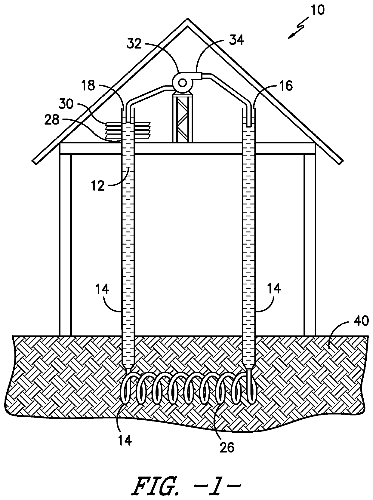
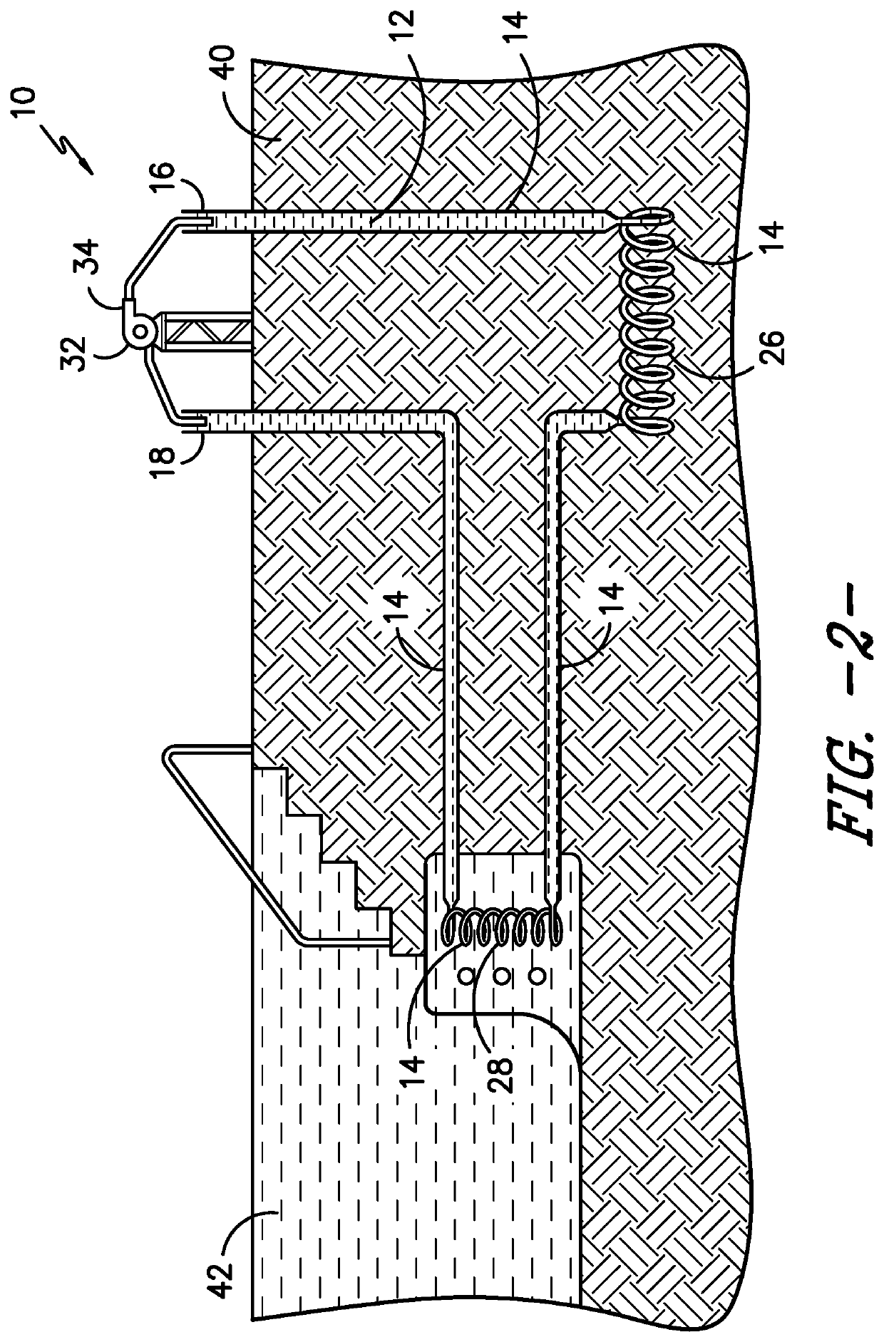
[0029]In a first embodiment of the present system 10, the first thermal exchange segment 26 is disposed below ground 40 and the system 10 includes a pump 34 which transfers fluid between conduit ends 16, 18, as in FIGS. 1 and 2. Thereby, heat may be transferred from or to the ground 40, which maintains a more consistent temperature during the year though surface conditions change. As a result, the present system 10 could be utilized to heat or cool an object or area based on the time of year and / or desired function.

Cooling

[0030]For example, regarding cooling, the system 10 could be arranged as in FIG. 1 to provide cooling to an attic space. Therein, the first end 16, second end 18, second thermal exchange segment 28, and a pump 34 are in the attic and the first thermal exchange segment 26 is below ground 40. In operation, fluid 12 is taken from the second end 18 and pumped into the first end 16, displacing fluid through a portion of the conduit 14 into the first thermal exchange seg...

second embodiment

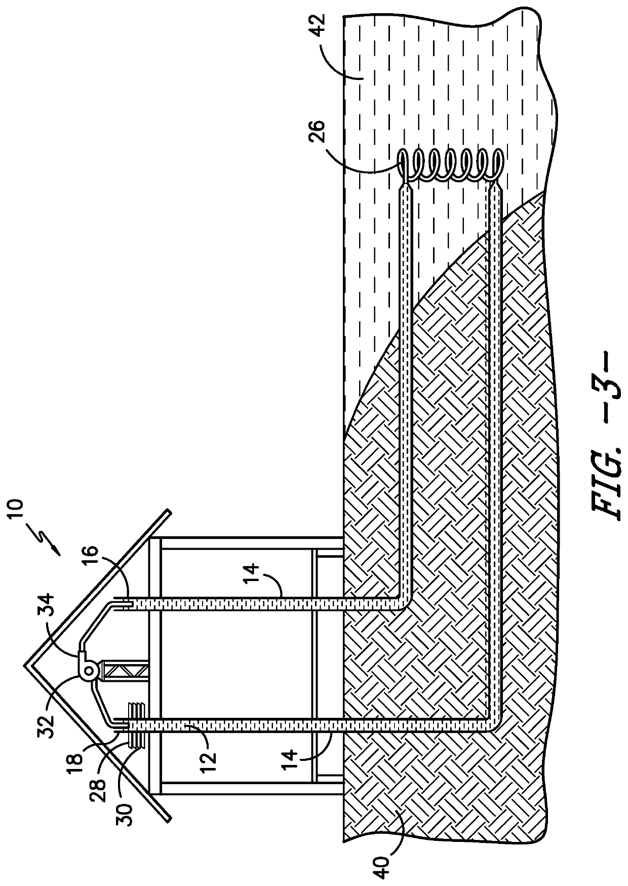
[0034]In a second embodiment, the first thermal exchange segment 26 may be disposed under water 42 rather than underground 40, as in FIGS. 3 and 9. Similar to the first embodiment, the system 10 can utilize the more consistent temperatures of bodies of water 42 versus surface temperatures to help heat or cool an object or an area, although such temperatures are not generally as consistent as underground. Examples of bodies of water 42 can include, but certainly are not limited to, barrels, ponds, lakes, streams, creeks, rivers, and reservoirs. Thereby, the present system 10 could be utilized to heat or cool an object or area based on the time of year and / or desired function.

Cooling

[0035]For example, the system 10 of FIG. 3 can be used to provide cooling to an attic by removing heat therefrom. Therein, the first thermal exchange segment 26 is located in a lake while the second thermal exchange segment 28 is located in the attic. In use, as fluid 12 which has already passed through th...

third embodiment

[0037]In a third embodiment, the first thermal exchange segment 26 may be disposed in shade 50 rather than below ground 40 or water 42, as in FIG. 10. Thereby, the system 10 can utilize the lowered temperature of a shaded region to cool an object in the sun. In FIG. 10, the first thermal exchange segment 26 is disposed in the shade 50 below a solar panel 52. In use, fluid 12 absorbs heat from the solar panel 52 in the second thermal exchange segment 28 before being drawn from the second end 18 and pumped to the first end 16. As the fluid 12 is pumped into the first end 16, fluid 12 already in the conduit 14 is displaced into the first thermal exchange segment 26 to give off heat and back into the second thermal exchange segment 28 to absorb more heat from the solar panel 52. Although the system 10 is described above as moving fluid 12 from the second end 18 into the first end 16, it is foreseen the system 10 could also move fluid in the opposite direction, from the first.

Alternative...


PUM


Abstract

A heat transfer system includes a conduit having open first and second ends, first and second thermal exchange segments disposed in-between and in fluid communication with the ends, and a means for adding fluid to the first end. The first thermal exchange segment is disposed underneath and in thermal communication with the ground, a body of water, or other location with a different temperature. The first and second ends are arranged above all other section of conduit and relative to one another so that they are communicating vessels and a change in fluid level in one changes the fluid level in the other. The means for adding fluid to the first end of the conduit causes fluid to flow freely from the first end to the second end and fluid level to rise in the second overcoming any hydrostatic pressure in the system without a pump disposed along the conduit.

Description

BACKGROUND[0001]The transfer of heat is both a necessary and critical mechanism within a broad range of systems and processes. In fact, modern society now relies on many systems and processes utilizing heat transfer and / or refrigeration for, among other things, climate control of our houses. Refrigeration and / or the transfer of heat in most systems and processes, however, is an energy-intensive exercise which can be costly, as it often involves the use of energy to generate heat or drive an electro-mechanical compressor.[0002]In addition to being costly and requiring large amounts of energy, many systems and processes involving refrigeration and / or the transfer of heat are also bulky and complex with many different parts, stages, and underlying principles that can limit their usefulness. In fact, due to their complexity, it is common for such systems and processes to have dedicated and trained personnel to design, install, maintain, and repair them.[0003]However, it is a common desi...

Claims


Application Information

Patent Timeline
IPC IPC(8): F24F5/00F24T10/15F24S20/40
CPCF24F2005/0057F24F5/0046F24T10/15F24S20/40F24V50/00F24F2005/0064F24T2010/50F24T50/00F24T10/10F24T10/40H02S40/42F24S20/02F24S90/10F28D20/0052F24D7/00E03B3/28Y02E10/10Y02E10/40F24S90/00F24D2200/11Y02E10/50Y02E60/14Y02A20/00Y02B10/20Y02B10/40H02S40/44Y02E10/60
Inventor SAAVEDRA, JOHN
Owner LOOK FOR THE POWER LLC
Why Eureka
Try Eureka