Lightweight Inflation Device

Inactive Publication Date: 2020-08-06
CAMP TEK
View PDF0 Cites 0 Cited by
  • Summary
  • Abstract
  • Description
  • Claims
  • Application Information

AI Technical Summary

Benefits of technology

[0005]In view of the foregoing, a method and apparatus are disclosed in selected embodiments of the present invention as including a lightweight inflation device. Such an inflation device may be or include a dual-stage compressor assembly selectively outputting a low-pressure airflow for efficiently inflating an air bladder. An inflation device in

Problems solved by technology

However, this size can make such devices somewhat unwieldy and difficult to transport.
Such motors consume significant electrical energy and often require access to a standard electrical outlet or a large battery pack.
While such conventional devices and methods for inflation have been satisfactory in some respects, they have also presented dr

Method used


Image

  • Lightweight Inflation Device
  • Lightweight Inflation Device
  • Lightweight Inflation Device

Examples


Example

[0043]It will be readily understood that the components of the present invention, as generally described and illustrated in the drawings herein, could be arranged and designed in a wide variety of different configurations. Thus, the following more detailed description of the embodiments of the system and method of the present invention, as represented in the drawings, is not intended to limit the scope of the invention, as claimed, but is merely representative of various embodiments of the invention. The illustrated embodiments of the invention will be best understood by reference to the drawings, wherein like parts are designated by like numerals throughout.

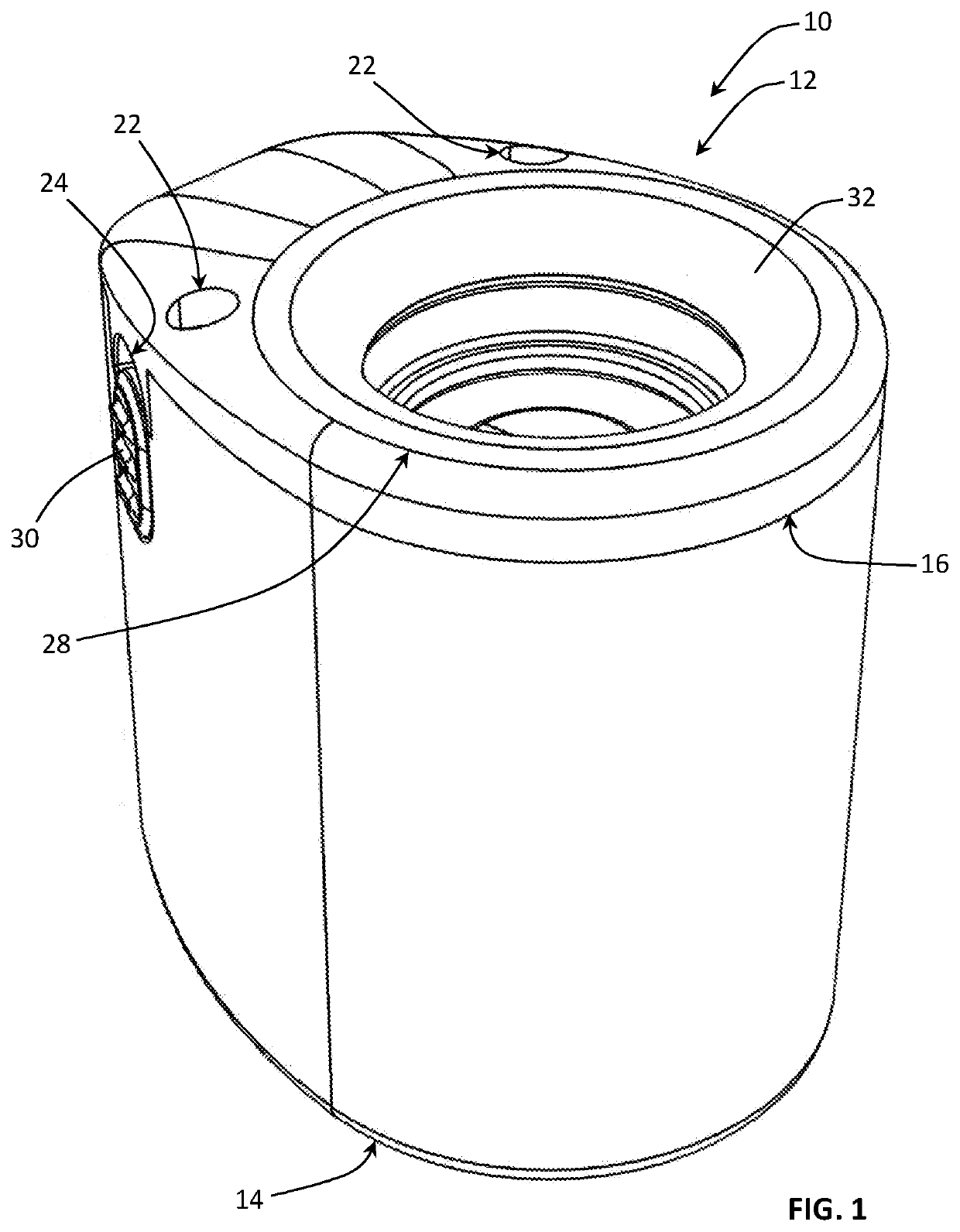
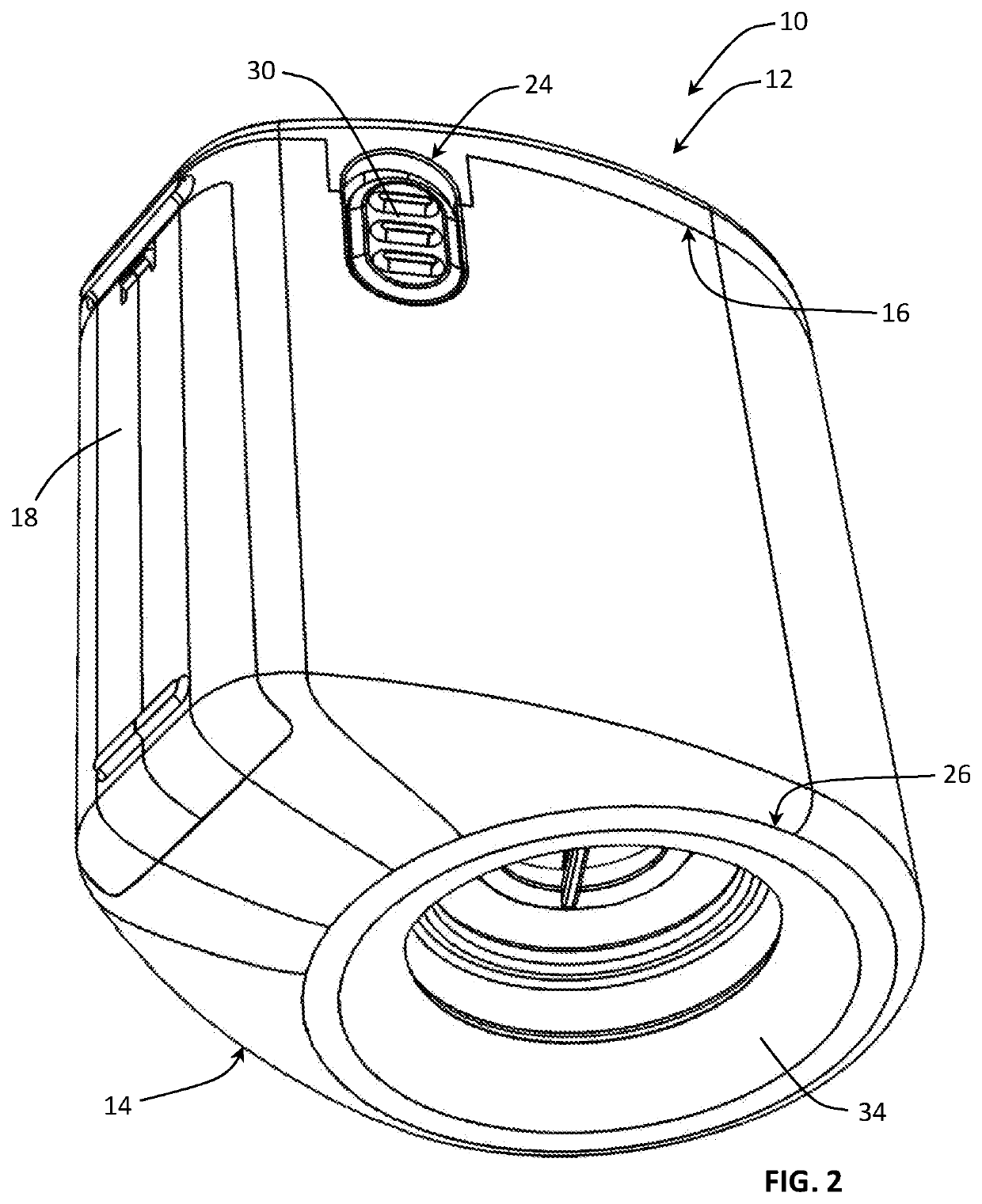
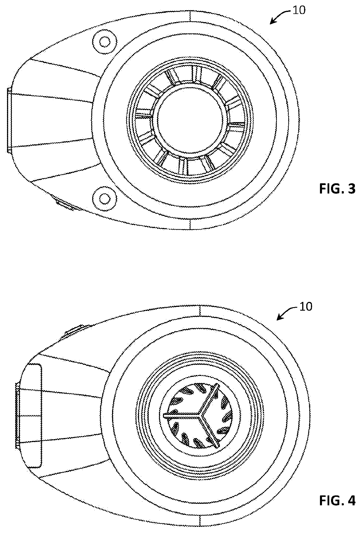
[0044]Referring to FIGS. 1-9, in selected embodiments, an inflation device 10 in accordance with the present invention may include a housing 12. A housing 12 may protect and support (e.g., provide mounting locations for) one or more interior components of an inflation device 10. Accordingly, a housing 12 may be or function as a ...


PUM


Abstract

An inflator for inflating an air mattress or the like may include a housing, a rotor, a stator, an electric motor, and at least one battery. The rotor may be contained within the housing and include a first circuit of fan blades and a second circuit of fan blades. The first and second circuits of fan blades may respectively generate centrifugal and axial flows of air when the electric motor rotates the rotor with respect to the stator. The stator may be contained within the housing and include a third circuit of fan blades. The at least one battery may power the electric motor. The at least one battery and the electric motor may also be contained within the housing.

Description

BACKGROUND1. The Field of the Invention[0001]This invention relates to inflation of air bladders and, more particularly, to novel systems and methods for a lightweight, readily portable, inflation device.2. The Background Art[0002]Various devices require inflation of one or more air bladders before they are ready to use. For example, sleeping pads, ultra-light air mattresses, pillows, or the like may include one or more air bladders that need to be inflated. Known devices and methods for inflating such devices include manual inflation and operating a pumping device (e.g., a manually powered pump or a pump driven by an electric motor).[0003]Manually powered pumping devices (e.g., bellows-style compression sacks) are often large enough to move a significant volume of air with each manual compression of the sack. However, this size can make such devices somewhat unwieldy and difficult to transport. Electrically powered pumping devices, on the other hand, frequently include a large and ...

Claims


Application Information

Patent Timeline
IPC IPC(8): F04D19/00F04D17/12F04D29/28F04D29/32F04D29/54
CPCF04D29/281F04D25/0673F04D29/542F04D17/12F04D19/007F04D29/329F04D19/002F04D17/025F04D25/084
Inventor POTRATZ, ROBERT STEPHEN
Owner CAMP TEK
Why Eureka
Try Eureka