Heater, fixing device, and image forming apparatus

a technology of fixing device and fixing belt, which is applied in the direction of heater elements, instruments, electrographic processes, etc., can solve the problems of increasing the rotation torque of the pressure roller of lubricant with an increased viscosity, and a part of the lubricant may leak from the fixing belt in the width direction,

Active Publication Date: 2020-08-06
RICOH KK
View PDF0 Cites 8 Cited by
  • Summary
  • Abstract
  • Description
  • Claims
  • Application Information

AI Technical Summary

Problems solved by technology

However, as the number of recording media that are conveyed through the fixing device increases, a part of the lubricant may leak from the fixing belt in the width direction thereof.
As the fixing device suffers from shortage of the lubricant over time, the frictional resistance between the heater and the fixing belt that slides over the heater may increase, increasing a driving torque between the fixing belt and a pressure roller that drives the fixing belt.
Hence, if the lubricant in a substantial amount is applied between the heater and the fixing belt to address decrease of the lubricant over time, when the fixing device is driven initially, the lubricant that has an increased viscosity may increase a rotation torque of the pressure roller.

Method used


Image

  • Heater, fixing device, and image forming apparatus
  • Heater, fixing device, and image forming apparatus
  • Heater, fixing device, and image forming apparatus

Examples


first embodiment

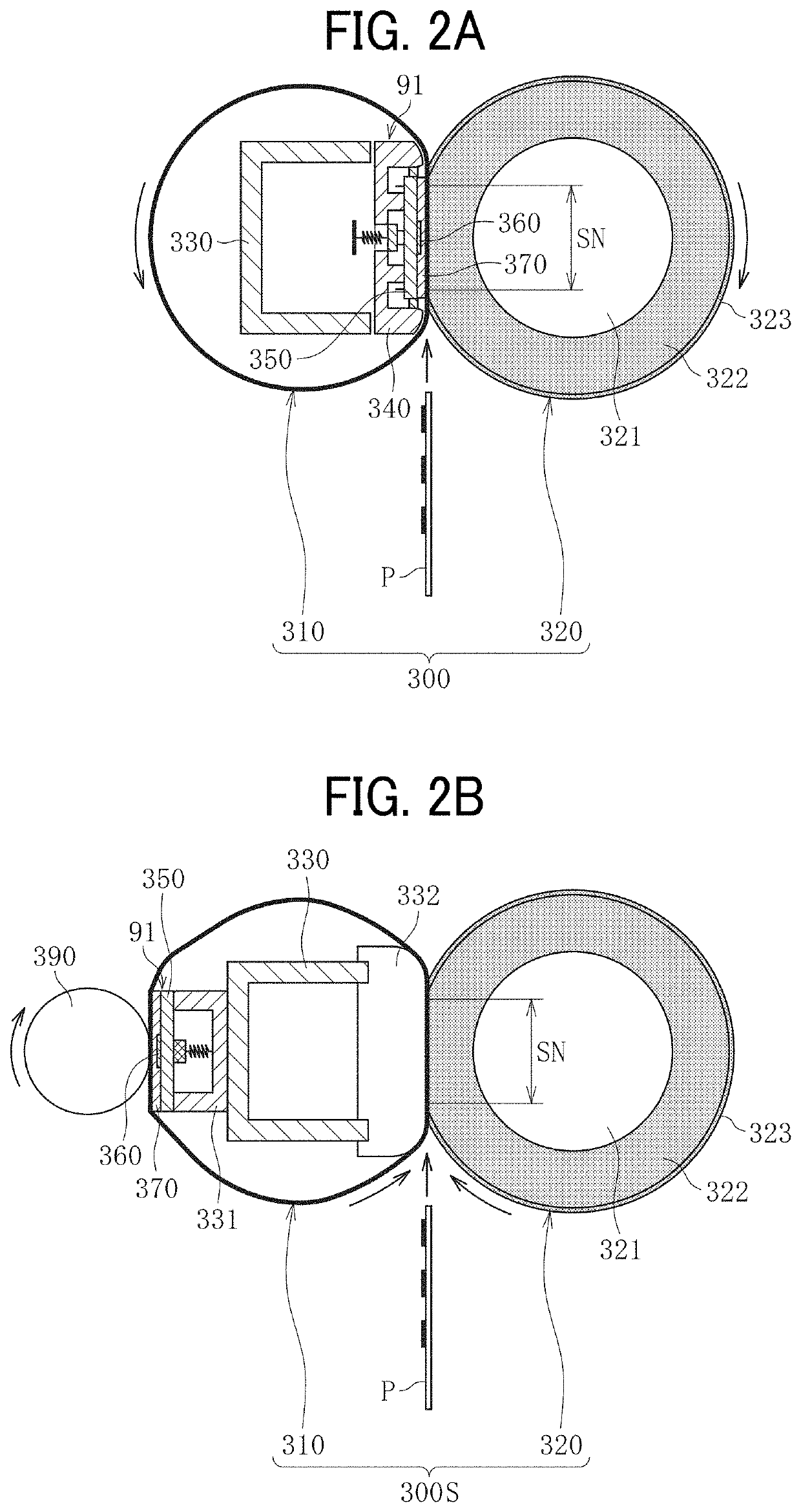
[0086]The following describes the construction of the heater 91 of the fixing device 300 which is also installable in the fixing devices 300S, 300T, and 300U. As illustrated in FIG. 2A, the heater 91 according to this embodiment heats the fixing belt 310 of the fixing device 300.

[0087]As illustrated in FIG. 2A, the fixing device 300 according to the first embodiment includes the fixing belt 310 that is thin and has a decreased thermal capacity and the pressure roller 320.

[0088]A detailed description is now given of a construction of the fixing belt 310.

[0089]The fixing belt 310 includes a tubular base that is made of polyimide (PI) and has an outer diameter of 25 mm and a thickness in a range of from 40 micrometers to 120 micrometers, for example.

[0090]The fixing belt 310 further includes a release layer serving as an outermost surface layer. The release layer is made of fluororesin, such as tetrafluoroethylene-perfluoroalkylvinylether copolymer (PFA) and polytetrafluoroethylene (P...

second embodiment

[0101]As illustrated in FIG. 2B, the fixing device 300S includes a pressing roller 390 disposed opposite the pressure roller 320 via the fixing belt 310. The pressing roller 390 and the heater 91 sandwich the fixing belt 310 such that the heater 91 heats the fixing belt 310.

[0102]The heater 91 is disposed inside the loop formed by the fixing belt 310. A supplementary stay 331 is mounted on a first side of the stay 330. A nip forming pad 332 serving as a nip former is mounted on a second side of the stay 330, which is opposite the first side thereof. The heater 91 is supported by the supplementary stay 331. The pressure roller 320 is pressed against the nip forming pad 332 via the fixing belt 310 to form the fixing nip SN between the fixing belt 310 and the pressure roller 320.

[0103]As illustrated in FIG. 2C, the fixing device 300T according to the third embodiment includes the heater 91 disposed inside the loop formed by the fixing belt 310. Since the fixing device 300T eliminates ...

third embodiment

[0122]A description is provided of a construction of a heater 91T according to the present disclosure.

[0123]FIG. 5 illustrates the heater 91T according to the third embodiment. As illustrated in FIG. 5, the heater 91T includes resistive heat generators 360T extended linearly in the longitudinal direction of the base 350 in two lines in parallel to each other. One lateral end of each of the resistive heat generators 360T in a longitudinal direction thereof, that are arranged in two lines, is connected to the electrodes 360c and 360d through the feeders 369c and 369a, respectively. The feeders 369a and 369c, having the decreased resistance value, are disposed on one lateral end of the base 350 in the longitudinal direction thereof. The electrodes 360c and 360d supply power to the resistive heat generators 360T.

[0124]Another lateral end of each of the resistive heat generators 360T in the longitudinal direction thereof is coupled to the feeder 369b such that the resistive heat generato...


PUM


Abstract

A heater includes a base and at least one resistive heat generator mounted on a face of the base. At least one electrode supplies power to the at least one resistive heat generator. A conductor couples the at least one electrode with the at least one resistive heat generator. A slide layer covers the at least one resistive heat generator and the conductor. The slide layer includes a projecting portion that defines a surface of the slide layer. The projecting portion is defined by a film thickness of at least one of the conductor and the at least one resistive heat generator. The projecting portion includes an upstream projection disposed opposite a lateral end of the base in a longitudinal direction of the base and a downstream projection disposed downstream from the upstream projection in a rotation direction of an endless belt that slides over the heater.

Description

CROSS-REFERENCE TO RELATED APPLICATION[0001]This patent application is based on and claims priority pursuant to 35 U.S.C. § 119(a) to Japanese Patent Application No. 2019-016136, filed on Jan. 31, 2019, in the Japan Patent Office, the entire disclosure of which is hereby incorporated by reference herein.BACKGROUNDTechnical Field[0002]Exemplary aspects of the present disclosure relate to a heater, a fixing device, and an image forming apparatus, and more particularly, to a heater incorporating a resistive heat generator, a fixing device incorporating the heater, and an image forming apparatus incorporating the heater.Discussion of the Background Art[0003]Related-art image forming apparatuses, such as copiers, facsimile machines, printers, and multifunction peripherals (MFP) having two or more of copying, printing, scanning, facsimile, plotter, and other functions, typically form an image on a recording medium according to image data by electrophotography.[0004]Such image forming appa...

Claims


Application Information

Patent Timeline
Patent Type & Authority Applications(United States)
IPC IPC(8): G03G15/20H05B3/03H05B3/00G03G15/00
CPCG03G2215/2032G03G15/80H05B2203/013G03G15/2053G03G2215/2048G03G15/2064H05B3/03H05B3/0019G03G2215/2035H05B3/06
Inventor INOUE, DAISUKEADACHI, TOMOYAFURUICHI, YUUSUKESOMEYA, YUKIMICHI
Owner RICOH KK
Why Eureka
Try Eureka