
Radio communication apparatus, method, program, non-transitory computer readable recording medium, and system

a radio communication and computer technology, applied in the field of radio communication apparatus, to achieve the effect of more appropriately performing control related to radio communication

Active Publication Date: 2020-08-06
NEC CORP
View PDF0 Cites 0 Cited by
  • Summary
  • Abstract
  • Description
  • Claims
  • Application Information

AI Technical Summary

Benefits of technology

The present invention can help improve control over radio communication when multiple transmission schemes are used. This can lead to better performance and efficiency in radio communication.

Problems solved by technology

However, a peak power in this scheme is higher than that in a single-carrier transmission scheme, and hence the coverage results in being small.

Method used


Image

  • Radio communication apparatus, method, program, non-transitory computer readable recording medium, and system
  • Radio communication apparatus, method, program, non-transitory computer readable recording medium, and system
  • Radio communication apparatus, method, program, non-transitory computer readable recording medium, and system

Examples


first example embodiment

3. First Example Embodiment

[0062]Next, a description will be given of a first example embodiment of the present invention with reference to FIGS. 4 to 14.

[0063]

[0064]First, with reference to FIG. 4, an example of a configuration of a system 1 according to the first example embodiment will be described. FIG. 4 is an explanatory diagram illustrating an example of a schematic configuration of the system 1 according to the first example embodiment. With reference to FIG. 4, the system 1 includes a base station 100 and terminal apparatuses 200.

[0065]Although two terminal apparatuses 200 (a terminal apparatus 200A and a terminal apparatus 200B) are illustrated in FIG. 4, the system 1 may include three or more terminal apparatuses 200. Here, when the two terminal apparatuses 200 need to be distinguished from each other, the terminal apparatuses 200 are described as the terminal apparatus 200A and the terminal apparatus 200B. However, when the two terminal apparatuses 200 need not be distin...

second example embodiment

4. Second Example Embodiment

[0170]Next, a description will be given of a second example embodiment of the present invention with reference to FIG. 15. The above-described first example embodiment is a concrete example embodiment, whereas the second example embodiment is a more generalized example embodiment.

[0171]

[0172]First, with reference to FIG. 15, an example of a configuration of a radio communication apparatus 400 according to the second example embodiment will be described. FIG. 15 is a block diagram illustrating an example of a schematic configuration of the radio communication apparatus 400 according to the second example embodiment. With reference to FIG. 15, the radio communication apparatus 400 includes a radio communication processing unit 410.

[0173]Concrete operations of the radio communication processing unit 410 will be described later in detail.

[0174]The radio communication processing unit 410 may be implemented with one or more processors (such as a BB processor an...


PUM


Abstract

In order to enable control related to radio communication to be performed more appropriately when radio transmission schemes coexist, a radio communication apparatus according to an example aspect of the present invention includes a radio communication processing unit configured to perform communication using a first radio transmission scheme within a frequency band, wherein the radio communication processing unit is configured to perform communication using a second radio transmission scheme within a bandwidth part of the frequency band, radio resources within the bandwidth part being allocable for communication using the second radio transmission scheme.

Description

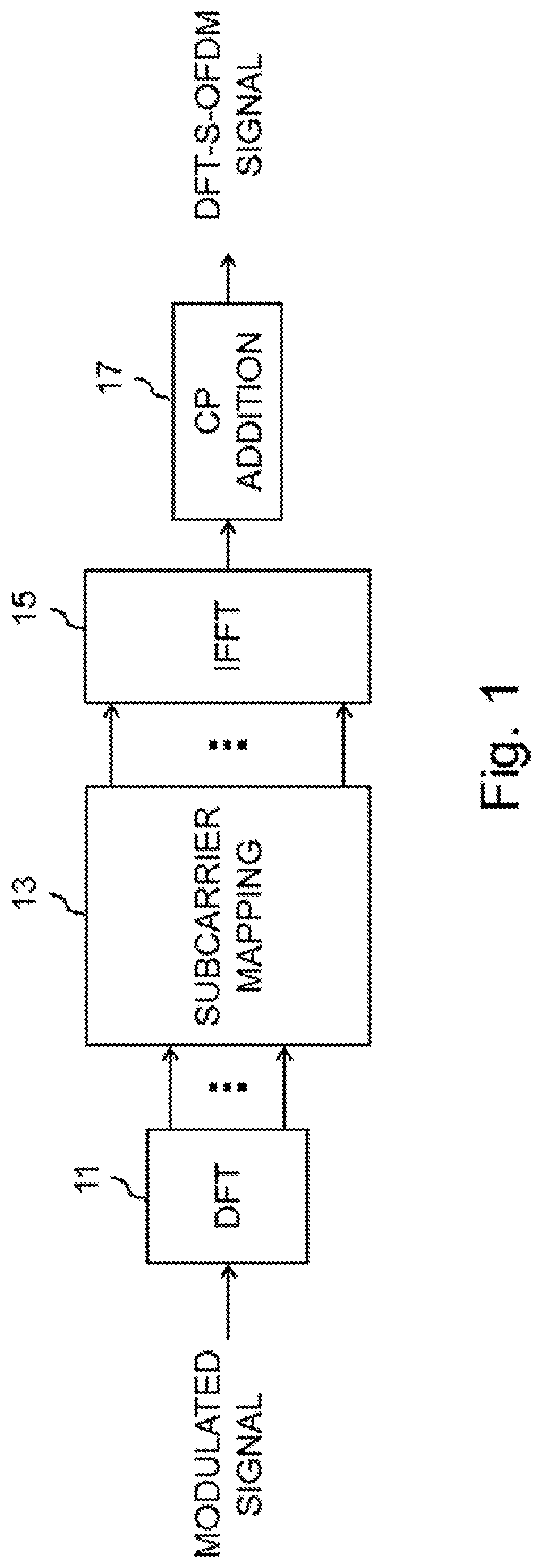
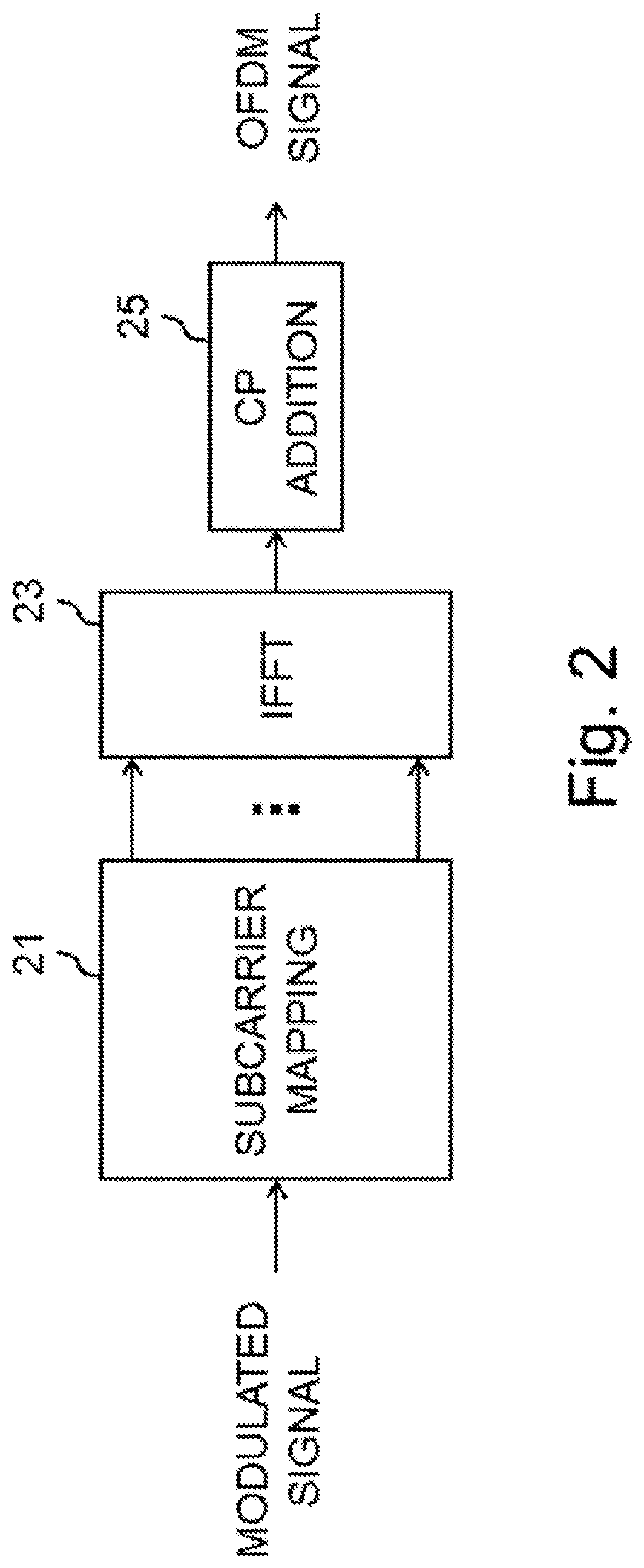
BACKGROUNDTechnical Field[0001]The present invention relates to a radio communication apparatus, a method, a program, a non-transitory computer readable recording medium, and a system.Background Art[0002]In Long Term Evolution (LTE) standardized in the 3rd Generation Partnership Project (3GPP), discrete Fourier transform spread orthogonal frequency division multiplexing (DFT-S-OFDM) is adopted as a radio transmission scheme to be used for uplink data transmission and reception (NPL 1). In DFT-S-OFDM, mapping of a discrete Fourier transform (DFT) output to an inverse fast Fourier transform (IFFT) input is limited to subcarriers that are contiguous on a frequency axis, to generate a single-carrier signal having a low peak power, which enables wide coverage.[0003]On the other hand, currently, standardization of New Radio (NR) supporting a wider frequency band than that of LTE is underway by 3GPP. In NR, to enable more flexible radio resource allocation, orthogonal frequency division mu...

Claims


Application Information

Patent Timeline
Patent Type & Authority Applications(United States)
IPC IPC(8): H04L5/00H04W72/04H04W72/08
CPCH04L5/0048H04W72/042H04L5/0007H04W72/085H04L27/26H04L5/0001H04L5/0098H04W72/1215H04W72/23H04W72/542
Inventor KAKURA, YOSHIKAZU
Owner NEC CORP
Learn More