Surgical drill guide aimed at locating ideal position for dental implants in edentulous patients

a surgical and drill guide technology, applied in the field of surgical drill guides aimed at locating the ideal position for dental implants in edentulous patients, can solve the problems of inability to achieve a correct anatomical orientation, difficulty in finding the right position for the insertion of dental implants, and inability to precisely anatomical position the dental implant is currently in,

Active Publication Date: 2020-08-13
ROSHKOVAN IGOR
View PDF0 Cites 1 Cited by
  • Summary
  • Abstract
  • Description
  • Claims
  • Application Information

AI Technical Summary

Benefits of technology

[0028]In other embodiment, the major perforated L track make up a supplemental short slot channels with extended positions corresponding to the natural position of absent t

Problems solved by technology

In this situation it is very difficult to locate the right position for the insertion of dental implants.
It is not currently possible to insert dental implant in a precise anatomical position.
This inability to achieve a correct anatomical orientation can occur for a number of reasons.
Most obviously, the patient's lack of any natural teeth prevents appropriated orientation.
The dental practitioner may choose the position to place the implant in the jaw at an angle to a preci

Method used


Image

  • Surgical drill guide aimed at locating ideal position for dental implants in edentulous patients
  • Surgical drill guide aimed at locating ideal position for dental implants in edentulous patients
  • Surgical drill guide aimed at locating ideal position for dental implants in edentulous patients

Examples


first embodiment

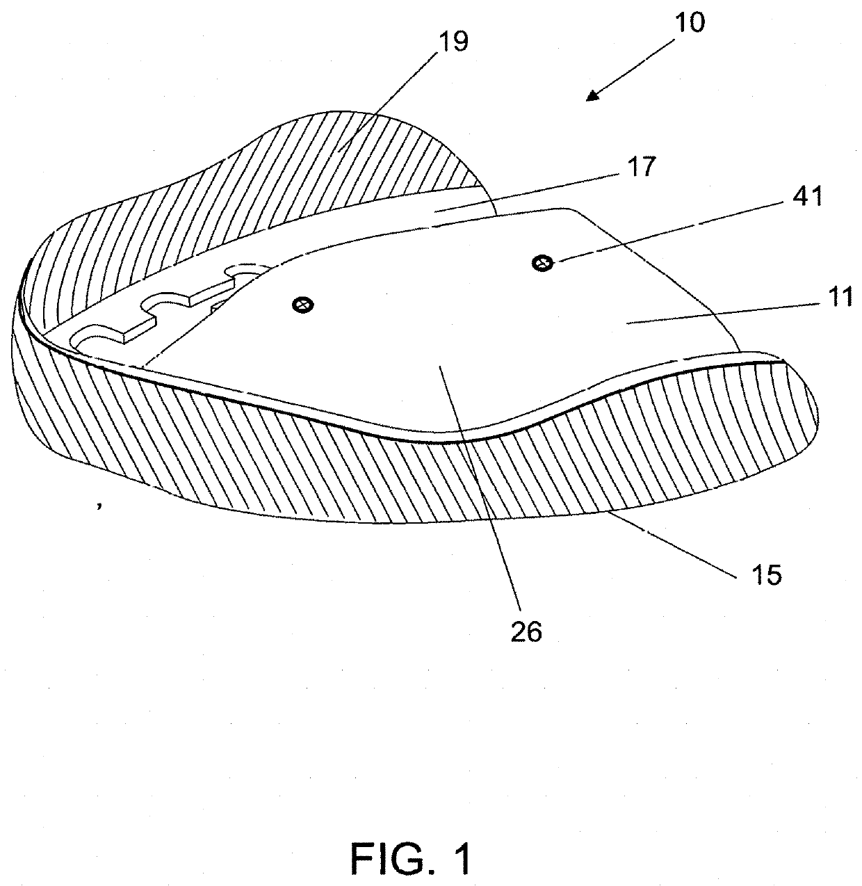
[0033]FIG. 1 is a perspective view of surgical guide for upper jaw in accordance with present invention.

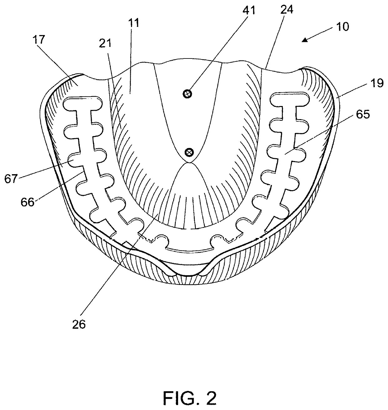
[0034]FIG. 2 is a top plan view of the tissue side of a surgical guide for upper jaw of FIG. 1.

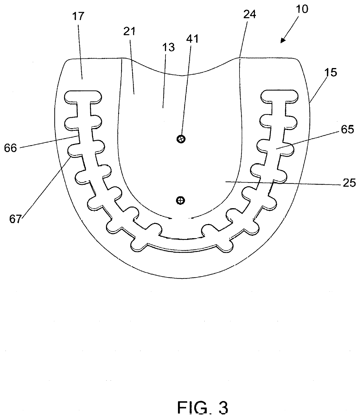
[0035]FIG. 3 is a bottom plan view of another embodiment in accordance with the present invention.

second embodiment

[0036]FIG. 4 is perspective view of surgical guide for lower jaw in accordance with present invention.

[0037]FIG. 5 is a top plan view of the second embodiment of surgical guide for lower jaw of FIG. 4.

[0038]FIG. 6 is a bottom plan view of the tissue side of surgical guide for lower jaw of FIG. 4.

[0039]FIG. 7 is a bottom view of the mounting devise of the present invention.

[0040]FIG. 8 is a bottom perspective view of the mounting devise of the present invention.

[0041]FIG. 9 is a perspective view of the embodiment of mounting devise for surgical guide for upper and lower jaw in accordance with present invention.

[0042]FIG. 10 is a top view of apparatus of FIG. 1 with the mounting device secured to the visible portion of perforated L track of present invention.

[0043]FIG. 11 is a top view of disassembled inner surface of present invention, showing the “hidden” contours of visible potion of L track.

[0044]FIG. 12 is a perspective view of a portion of major perforated L track, for which one...

embodiment 10

[0078]Referring to FIG. 1, a surgical drill guide for upper jaw 10 is generally fan-shaped in plan. One embodiment 10 includes a base portion 17. The base is normally defined by an arcuated buccal wall 19 and this wall 19 extends mostly vertical from the base portion 17 and the created outer edge 15. The upper surgical guide comprises at least two plates: top plate 11 and bottom plate (not shown), which are connected together by means of screws 41. In addition, the present embodiment 10 is provided with a palatal upwardly convex extending arch surface 26.

[0079]Preferably, each surgical guide consists of at least 2 plates: top plate 11 and 12 respectively and bottom plate 13 and 14 respectively, which are connected together by means of screws 41 (see FIGS. 1-6);

[0080]As illustrated in FIG. 2 surgical drill guide for upper jaw 10 contains base portion 17 in which is located the major perforated L track 65, consisting of perforated portion and narrowed portion 66 and added by supplemen...


PUM


Abstract

This document describes a set of surgical drill guides for the upper and lower jaw, the guides aimed at locating the ideal position for dental implants in edentulous patients. The guides are made up of a surgical stent material from metal or other rigid material that is aligned to provide support and stability of fully edentulous upper and lower jaw to orient surgical drills in the area of operation. The present embodiment comprises a U-shape metal plate provided form or shaped resembling a toothless upper or lower jaw and containing a top surface of the surgical stent that is contacting the soft tissue of maxilla or mandibula and the bottom surface of the stent that has the same shape as a top one.

Description

BACKGROUND—PRIOR ART[0001]This embodiment is in field of dental prostheses and methods and apparatus for performing dental fixed implant retained bridges, removable overdentures or screw retained overdentures and for set up dental intraoral prostheses in the mouth of patients.[0002]This disclosure concerns improved dental care for edentulous patients, toothless patients or patients lacking teeth. The inventions include a novel surgical guide aimed at locating ideal position for dental implants in edentulous patients. This embodiment relates particularly to surgical drill guide device aimed at locating ideal position for dental implants in patients without teeth and providing an improved surgical guide for installing and insertion of dental implants. This embodiment has a reference to the portion of dental device, methods and apparatus as a surgical guide aimed at locating the ideal position for dental implants in edentulous patients that is particularly adapted for dental use, which...

Claims


Application Information

Patent Timeline
IPC IPC(8): A61C1/08A61C8/00
CPCA61C8/0089A61B17/17A61C1/084
Inventor ROSHKOVAN, IGOR
Owner ROSHKOVAN IGOR
Why Eureka
Try Eureka