Clutch Arrangement

Inactive Publication Date: 2020-08-13
ZF FRIEDRICHSHAFEN AG
View PDF0 Cites 0 Cited by
  • Summary
  • Abstract
  • Description
  • Claims
  • Application Information

AI Technical Summary

Benefits of technology

The patent text describes a design for a clutch piston and related components that prevents the flow of fluid between two pressure chambers when they are connected to multiple pressure lines. This prevents interference between the pressure lines and ensures proper functioning of the clutch.

Problems solved by technology

Owing to different modes of operation in 3-line systems and 2-line systems, and resulting structural differences, the number of possible identical parts is limited.
This is reflected in increased manufacturing outlay and thus in higher costs.

Method used


Image

  • Clutch Arrangement
  • Clutch Arrangement
  • Clutch Arrangement

Examples


Embodiment Construction

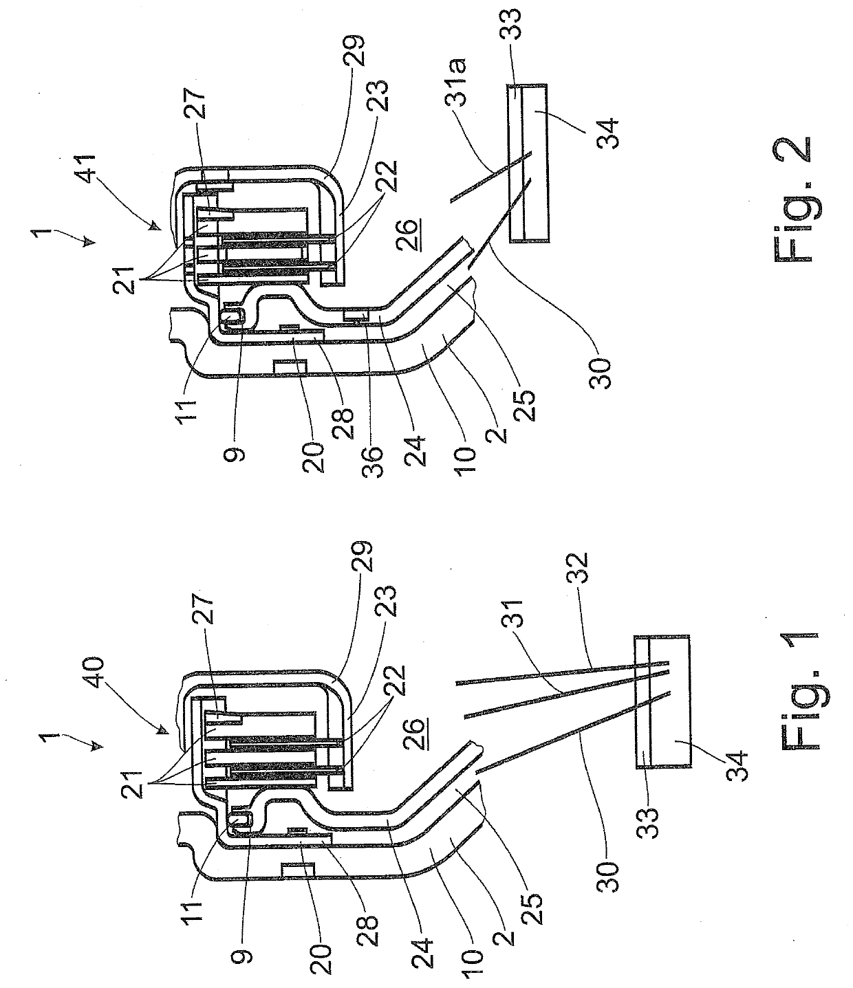
[0020]FIG. 1 or 2 illustrates in each case a clutch arrangement 1 provided in a clutch housing 2, which is indicated by a housing cover 10. The clutch arrangement 1 may be part of a hydrodynamic torque converter, of a hydraulic clutch or of a wet-running clutch.

[0021]In a manner which is not shown, the clutch housing 2 may be connected rotationally conjointly by attachment elements 7, shown in FIG. 5, to a drive (not shown) such as an internal combustion engine, and said clutch housing performs a rotational movement about a central axis 8 when a rotational movement is introduced by the drive.

[0022]The housing cover 10 serves for accommodating a drive-side clutch element carrier 20, which serves as input 28 of the clutch arrangement 1 and for rotationally conjointly holding drive-side clutch elements 21, which are functionally assigned at least one output-side clutch element 22, which engages rotationally conjointly into an output-side clutch element carrier 23. The drive-side clutch...


PUM


Abstract

A clutch arrangement having multiple pressure lines, connected to pressure chambers provided in a clutch housing, a first pressure chamber exerts load on a clutch piston and a second pressure chamber accommodates a clutch element and feeds fluid for cooling the at least one clutch element. The two pressure chambers are separated from one another in a pressure-tight fashion in the region of the clutch piston. The clutch piston and / or a component assigned to the clutch piston is designed such that, when at least one pressure chamber is connected to at least two pressure lines, a flow connection between the two pressure chambers is prevented, whereas, when each pressure chamber is connected to only one pressure line, a flow connection can be produced between the two pressure chambers by virtue of the clutch piston, and / or the component assigned to the clutch piston, being formed with a passage.

Description

BACKGROUND OF THE INVENTION1. Field of the Invention[0001]The invention relates to a clutch arrangement having a multiplicity of pressure lines connected to at least two pressure chambers provided in a clutch housing, of which a first pressure chamber serves for exerting load on a clutch piston and a second pressure chamber serves for accommodating at least one clutch element of a clutch unit and for feeding fluid for cooling the at least one clutch element, wherein the two pressure chambers are separated from one another in at least substantially pressure-tight fashion in the region of extent of the clutch piston.2. Description of Related Art[0002]A clutch arrangement of said type is known from DE 11 2008 003 612 B4. The clutch arrangement accommodated in the clutch housing of a hydrodynamic torque converter has a radially outer clutch element carrier held on a turbine wheel and a radially inner clutch element carrier supported by a torsional vibration damper. Each clutch element c...

Claims


Application Information

Patent Timeline
IPC IPC(8): F16D25/06F16D25/12
CPCF16D25/06F16D25/123F16D25/0638
Inventor SCHNEIDER, CHRISTIANPAONE, ALESSIOMENEBROKER, TROYWU, RICHARD
Owner ZF FRIEDRICHSHAFEN AG
Why Eureka
Try Eureka