
Optical projecting apparatus

Active Publication Date: 2015-07-09
DELTA ELECTRONICS INC
View PDF3 Cites 0 Cited by
  • Summary
  • Abstract
  • Description
  • Claims
  • Application Information

AI Technical Summary

Benefits of technology

The patent text describes an optical projecting apparatus that is made up of two digital micro-mirror devices (DMDs) and at least one solid state light source. The technical effects of this invention are high luminance efficiency, vivid color brilliance, and low cost.

Problems solved by technology

However, the projector using one chip DLP technology can't meet requirement of luminance and color saturation.
The projector using one chip DLP technology is limited to serial color modulation, so that luminance efficiency thereof is decreased.
Besides, color breaking is brought by mechanical structure limitation of the color wheel.
Namely, in some states, observer shall sight unpredictable scrambled color because serial color modulation can't meet condition of persistence of vision, so that the projector mentioned above can't satisfy with high-level application.
However, the projector having three DMDs and peripheral optical component corresponding to the each DMD is bulky and its manufacturing cost is then increased.

Method used


Image

  • Optical projecting apparatus
  • Optical projecting apparatus
  • Optical projecting apparatus

Examples


first embodiment

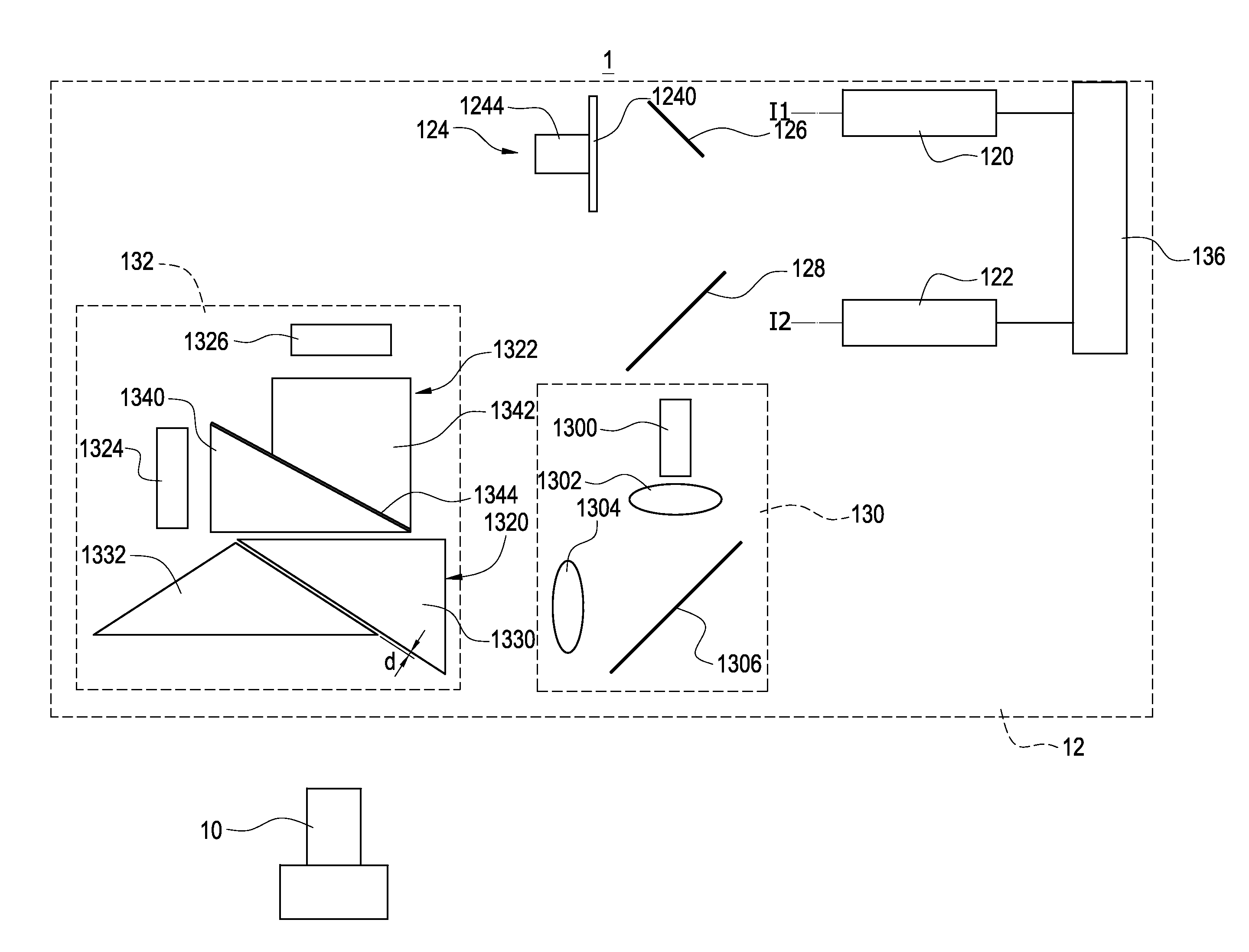
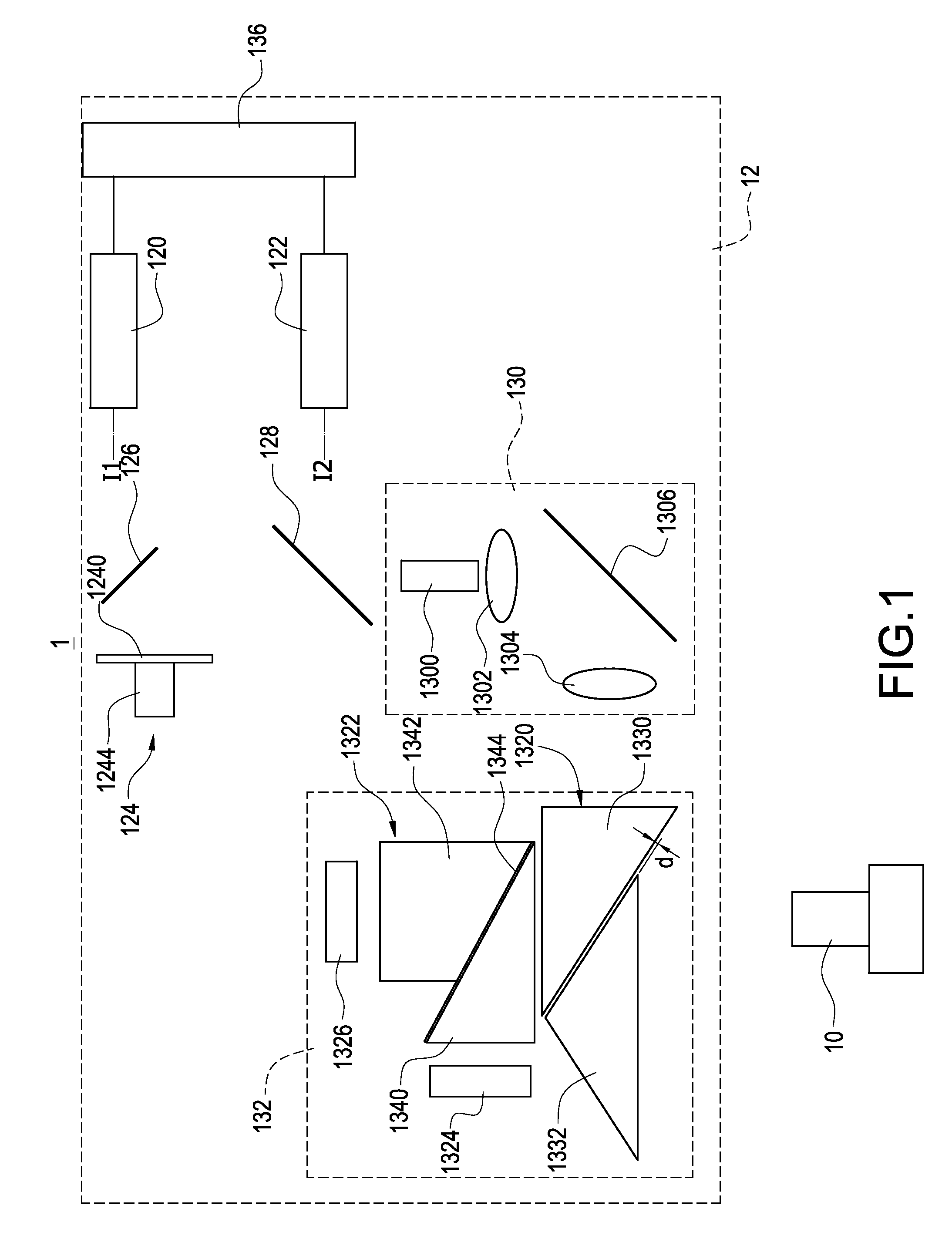
[0024]Reference is made to FIG. 1, which is a schematic diagram of an optical projecting system according to the present invention. The optical projecting system 1 includes a projecting lens 10 and an optical projecting apparatus 12. The optical projecting apparatus 12 projects a light beam to a screen (not shown) via the projecting lens 10.

[0025]The optical projecting apparatus 12 includes a first solid state light generator 120, a second solid state light generator 122, a first wavelength-converting module 124, a first color-splitting filter 126, a second color-splitting filter 128, an optical module 130, a spatial light modulating module 132, and a controller 136.

[0026]The first solid state light generator 120 generates a first light beam and has a first optical axis H. The first optical axis I1 is a symmetrical axis for illuminant intensity of the first light beam in spatial distribution. In this embodiment, the first light beam generated by the first solid state light generator...

second embodiment

[0051]Reference is made to FIG. 7, which is a schematic diagram of an optical projecting system according to the present invention. The optical projecting system 2 includes a projecting lens 10 and an optical projecting apparatus 22. The optical projecting apparatus 22 projects a light beam to a screen (not shown) via the projecting lens 10.

[0052]The optical projecting apparatus 22 includes a solid state light generator 220, a wavelength-converting module 224, a first color filter 126, a second color filter 228, an optical module 130, a spatial light modulating module 132, a first reflector 234, and a second reflector 236.

[0053]The solid state light generator 220 having an optical axis I is configured to generate a light beam. The optical axis I is a symmetrical axis for illuminant intensity of the first light beam in spatial distribution. In this embodiment, the light beam generated from the solid state light generator 220 has a blue spectrum. In the practical applications, however...


PUM


Abstract

An optical projecting apparatus is used for providing a projecting light to a screen via a projecting lens, the optical projecting apparatus and the projecting lens collectively form an optical projecting system. The optical projecting apparatus includes a first solid state light generator generating a first light beam, a second solid state light generator generating a second light beam, a first wavelength-converting module, and a spatial light modulating module. The first wavelength-converting module convers the first light beam into a wavelength-converted light. The spatial light modulating module splits the wavelength-converted light into a third light beam and a fourth light beam, and transmits the second light beam, the third light beam, and the fourth light beam to the screen via the projecting lens.

Description

BACKGROUND OF THE INVENTION[0001]1. Field of the Invention[0002]The present invention relates to an optical projecting apparatus, and in particular to an optical projecting apparatus assembled by two digital micro-mirror devices (DMDs) and at least one solid state light sources.[0003]2. Description of Related Art[0004]Projector having light source consisted of laser and fluorescent material becomes popular. However, laser is expansive so that most of projectors having light source mentioned above adopt one chip digital light processing (DLP) technology to reduce cost.[0005]Projector using one chip DLP technology includes only one digital micro-mirror device (DMD) to modulate image, so that a color wheel must be adopted to generate spectrums having various colors. For example, white spectrum generally composed of red spectrum, green spectrum, and blue spectrum. The spectrums are then serially transmitted to the DMD and modulated thereby, and then observers can sight colors correspond...

Claims


Application Information

Patent Timeline
IPC IPC(8): H04N9/31B81B5/00H04N5/74
CPCH04N9/3161H04N9/3158H04N9/3164H04N9/3155B81B2201/042B81B5/00G02B27/14G02B5/04H04N5/7458H04N9/3182G02B26/008G02B27/1026G03B21/2066G03B21/28
Inventor WANG, BORHSU, MING-YO
Owner DELTA ELECTRONICS INC
Learn More