Method of making a metal injection molded ammunition cartridge

a technology of metal injection molding and ammunition cartridges, applied in the field of ammunition, can solve the problems of long manufacturing time and limit the use of materials

Active Publication Date: 2020-08-13
TRUE VELOCITY IP HLDG LLC
View PDF0 Cites 55 Cited by
  • Summary
  • Abstract
  • Description
  • Claims
  • Application Information

AI Technical Summary

Benefits of technology

[0010]injecting a metal composition into the ammunition cartridge mold to form a metal injection molded ammunition cartridge, wherein the metal composition comprises 2-16% Ni; 10-20% Cr; 0-5% Mo; 0-0.6% C; 0-6.0% Cu; 0-0.5% Nb+Ta; 0-4.0% Mn; 0-2.0% Si and the balance Fe; 2-6% Ni; 13.5-19.5% Cr; 0-0.10% C; 1-7.0% Cu; 0.05-0.65% Nb+Ta; 0-3.0% Mn; 0-3.0% Si and the balance Fe; 3-5% Ni; 15.5-17.5% Cr; 0-0.07% C; 3-5.0% Cu; 0.15-0.45% Nb+Ta; 0-1.0% Mn; 0-1.0% Si and the balance Fe; 10-14% Ni; 16-18% Cr; 2-3% Mo; 0-0.03% C; 0-2% Mn; 0-1% Si and the balance Fe; 12-14% Cr; 0.15-0.4% C; 0-1% Mn; 0-1% Si and the balance Fe; 16-18% Cr; 0-0.05% C; 0-1% Mn; 0-1% Si and the balance Fe; 3-12% aluminum, 2-8% vanadium, 0.1-0.75% iron, 0.1-0.5% oxygen, and the remainder titanium; or 6% aluminum, about 4% vanadium, about 0.25% iron, about 0.2% oxygen, and the remainder titanium, and removing the metal injection molded ammunition cartridge from the ammunition cartridge mold.
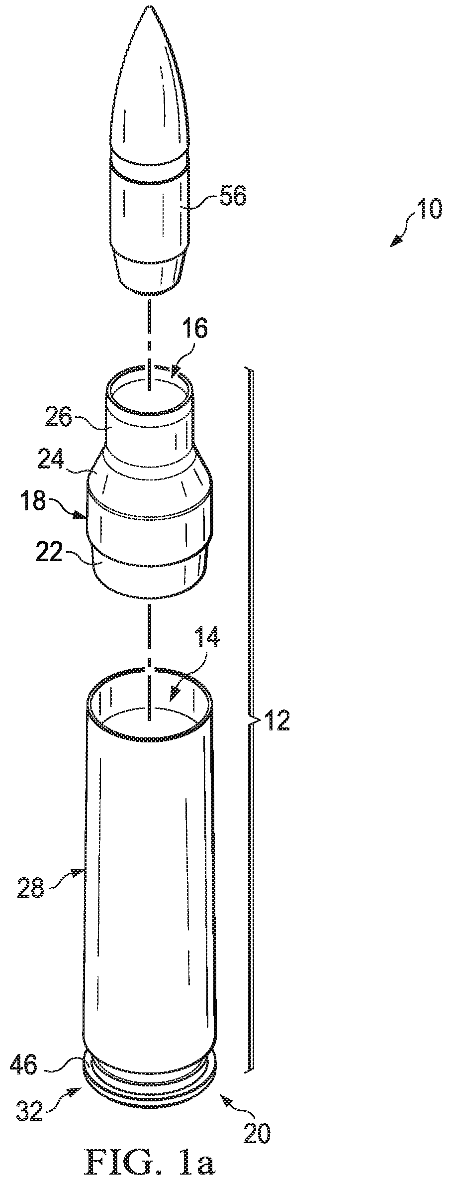
[0011]The present invention provides a method of making a metal injection molded ammunition cartridge comprising the steps of: providing an ammunition cartridge mold comprising a bottom portion having a primer recess extending into the bottom portion adapted to receive a primer, a flash hole positioned in the primer recess through the bottom surface; side walls extending from the bottom portion to a nose end aperture, wherein a propellant chamber is formed between the nose end aperture and the bottom surface; injecting a metal composition into the ammunition cartridge mold to form a metal injection molded ammunition cartridge, wherein the metal composition comprises a) 2-16% Ni; 10-20% Cr; 0-5% Mo; 0-0.6% C; 0-6.0% Cu; 0-0.5% Nb+Ta; 0-4.0% Mn; 0-2.0% Si and the balance Fe; b) 2-6% Ni; 13.5-19.5% Cr; 0-0.10% C; 1-7.0% Cu; 0.05-0.65% Nb+Ta; 0-3.0% Mn; 0-3.0% Si and the balance Fe; c) 3-5% Ni; 15.5-17.5% Cr; 0-0.07% C; 3-5.0% Cu; 0.15-0.45% Nb+Ta; 0-1.0% Mn; 0-1.0% Si and the balance Fe; d) 10-14% Ni; 16-18% Cr; 2-3% Mo; 0-0.03% C; 0-2% Mn; 0-1% Si and the balance Fe; e) 12-14% Cr; 0.15-0.4% C; 0-1% Mn; 0-1% Si and the balance Fe; f) 16-18% Cr; 0-0.05% C; 0-1% Mn; 0-1% Si and the balance Fe; g) 3-12% aluminum, 2-8% vanadium, 0.1-0.75% iron, 0.1-0.5% oxygen, and the remainder titanium; or h) about 6% aluminum, about 4% vanadium, about 0.25% iron, about 0.2% oxygen, and the remainder titanium, and removing the metal injection molded ammunition cartridge from the ammunition cartridge mold.

Problems solved by technology

Shortcomings of the known methods of producing ammunition cartridges include the limitation of materials that can be used and the lengthy time for manufacturing.

Method used


Image

  • Method of making a metal injection molded ammunition cartridge
  • Method of making a metal injection molded ammunition cartridge
  • Method of making a metal injection molded ammunition cartridge

Examples


Embodiment Construction

[0034]While the making and using of various embodiments of the present invention are discussed in detail below, it should be appreciated that the present invention provides many applicable inventive concepts that can be embodied in a wide variety of specific contexts. The specific embodiments discussed herein are merely illustrative of specific ways to make and use the invention and do not delimit the scope of the invention.

[0035]As used herein the term “shell,”“bullet” and “projectile” are used interchangeably and denote a projectile that is positioned in an ammunition cartridge until it is expelled from a gun, rifle, or the like and propelled by detonation of a powdered chemical propellant or other propellant that may be non-powdered, solid, gaseous or gelatin. And includes payload-carrying projectiles contains shot, an explosive or other filling, though modern usage sometimes includes large solid projectiles properly termed shot (AP, APCR, APCNR, APDS, APF SD S and proof shot).

[0...


PUM

PropertyMeasurementUnit
thicknessaaaaaaaaaa
thicknessaaaaaaaaaa
thicknessaaaaaaaaaa

Abstract

The present invention provides a method of making a metal injection molded ammunition cartridge comprising the steps of: providing an ammunition cartridge mold comprising a bottom portion having a primer recess extending into the bottom portion adapted to receive a primer, a flash hole positioned in the primer recess through the bottom surface; side walls extending from the bottom portion to a nose end aperture, wherein a propellant chamber is formed between the nose end aperture and the bottom surface; injecting a metal composition into the ammunition cartridge mold to form a metal injection molded ammunition cartridge; and removing the metal injection molded ammunition cartridge from the ammunition cartridge mold.

Description

CROSS-REFERENCE TO RELATED APPLICATIONS[0001]This application is a Continuation Application of co-pending U.S. patent application Ser. No. 16 / 017,142 filed Jun. 25, 2018, which is a Continuation Application of U.S. patent application Ser. No. 14 / 863,800 filed Sep. 24, 2015, now U.S. Pat. No. 10,041,770, which is a Continuation Application of U.S. patent application Ser. No. 14 / 011,202 filed Aug. 27, 2013, now U.S. Pat. No. 9,546,849, which is a Continuation Application of U.S. patent application Ser. No. 13 / 292,843 filed Nov. 9, 2011, now U.S. Pat. No. 8,561,543, which claims the benefit of U.S. patent application Ser. No. 61 / 456,664 filed Nov. 10, 2010, all of which are incorporated herein by reference.TECHNICAL FIELD OF THE INVENTION[0002]The present invention relates in general to the field of ammunition, specifically to compositions of matter and methods of making metal cartridge cases by metal injection molding.STATEMENT OF FEDERALLY FUNDED RESEARCH[0003]None.INCORPORATION-BY-R...

Claims


Application Information

Patent Timeline
Patent Type & Authority Applications(United States)
IPC IPC(8): F42B5/02B29C45/00F42B5/36F42B5/26F42B5/285
CPCF42B5/26F42B5/36B29C45/0046F42B5/285F42B5/02F42B10/44F42B12/34F42B12/78F42B12/74F42B12/367F42B12/44F42B12/22F42B12/38F42B10/56F42B12/48F42B14/064F42B14/061F42B15/00B22F3/225C22C33/0285C22C1/0458
Inventor BURROW, LONNIE
Owner TRUE VELOCITY IP HLDG LLC
Why Eureka
Try Eureka