Supercharge Your Innovation With Domain-Expert AI Agents!

Torque driver integrated with a valve core removal tool

a technology of torque driver and valve core, which is applied in the direction of wrenches, valve details, valve arrangements, etc., can solve the problems of tool failure to alleviate the problem, too little torque, and refrigerant leakage from the system

Inactive Publication Date: 2020-08-27
ANDERSON BRASS
View PDF0 Cites 3 Cited by
  • Summary
  • Abstract
  • Description
  • Claims
  • Application Information

AI Technical Summary

Benefits of technology

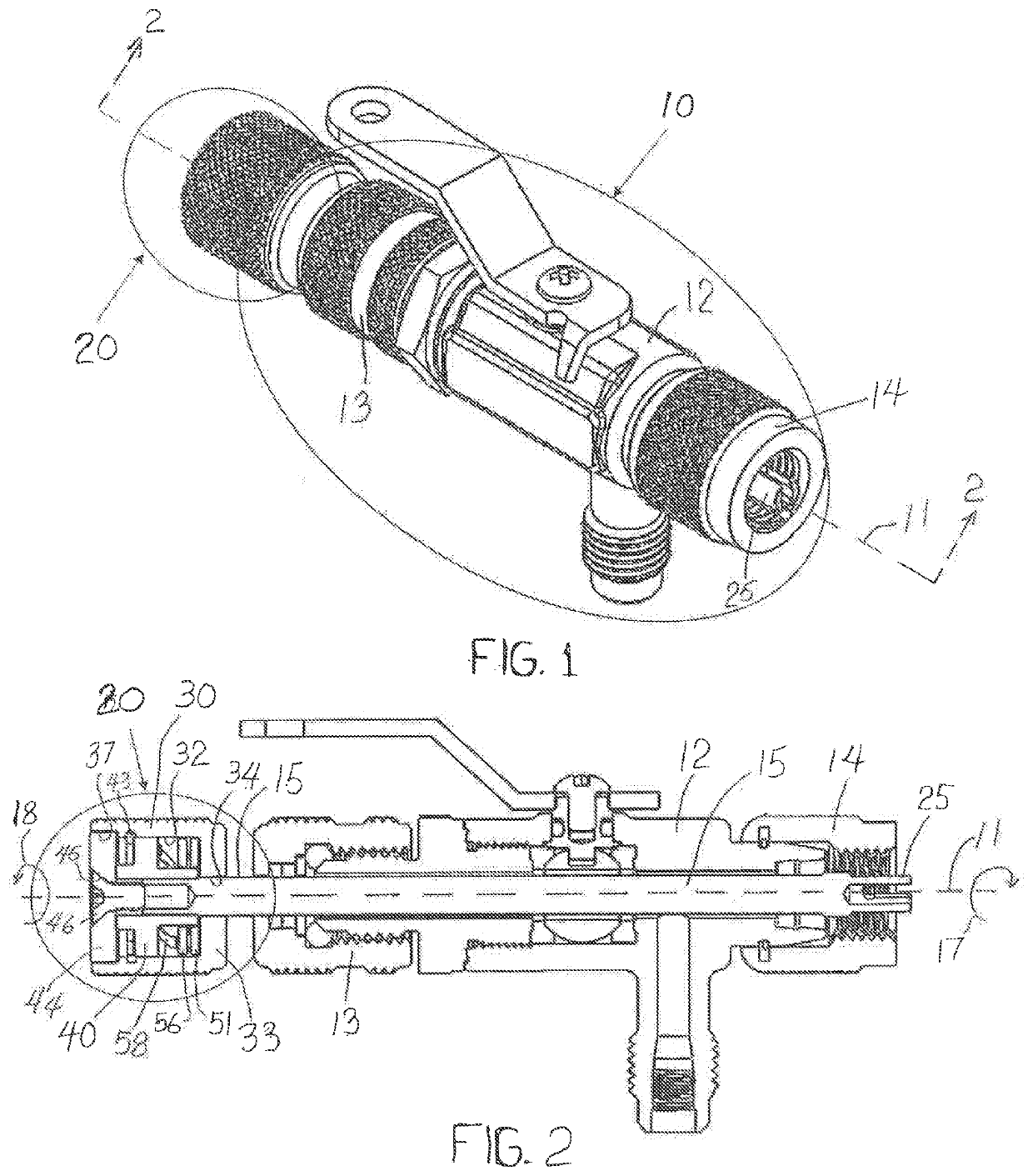
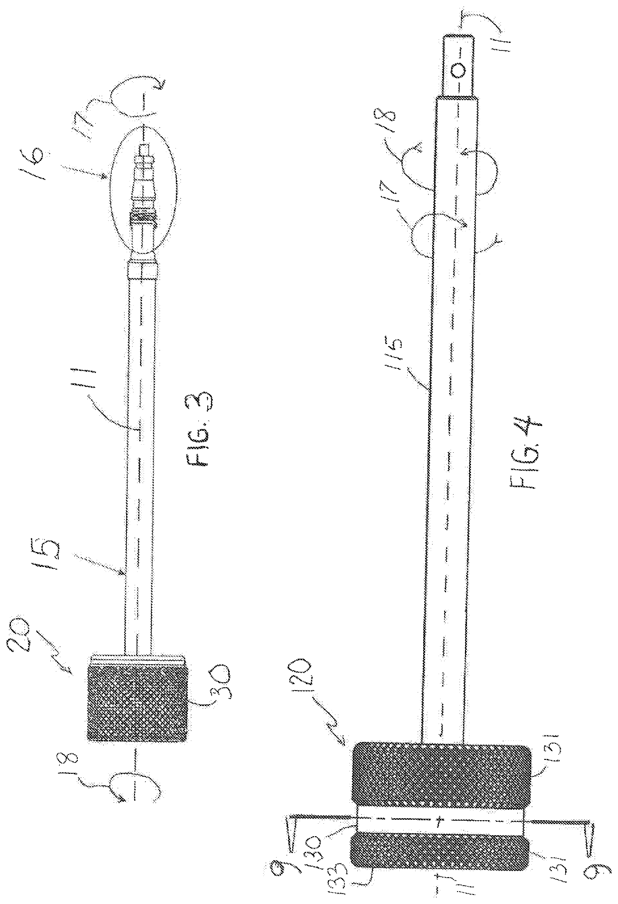
The present invention relates to an apparatus for removing and installing valve cores from sealed systems that are not at atmospheric pressure. The technical effects of this invention include providing a secure and efficient way to remove and install valve cores without compromising the refrigerant leakage or damaging the valve threads. The apparatus can accommodate different valve core structures and is easy to use with little training required for operators. The invention also addresses the need for a secure and efficient way to remove and install valve cores from sealed systems that are not at atmospheric pressure.

Problems solved by technology

However, unless a skilled operator is manipulating these tools to install the valve core with the appropriate amount of torque, too little torque allows refrigerant to leak from the system, while too much torque damages the threads of the valve, which then must be replaced once the valve core fails and needs to be removed.
But this tool fails to alleviate the issues noted above.
Yet this tool also fails to alleviate the issues noted above.
Having personnel on hand who are sufficiently competent to manipulate the valve removal tool with just the appropriate amount of torque also poses problems.
Less competent personnel take longer to engage and remove the defective valve core and install the replacement valve core.
Such delays add additional cost to the performance of these tasks.
However, until this secure placement has been effected, workers should not be permitted access to the HVAC system.

Method used


Image

  • Torque driver integrated with a valve core removal tool
  • Torque driver integrated with a valve core removal tool
  • Torque driver integrated with a valve core removal tool

Examples


Embodiment Construction

[0029]Reference will now be made in detail to present exemplary embodiments of the invention, wherein one or more examples of which are illustrated in the accompanying drawings. The detailed description uses numerical and / or letter designations to refer to features in the drawings. Like or similar designations in the drawings and description have been used to refer to like or similar parts of the embodiments of the invention.

[0030]Each example is provided by way of explanation of the invention, not limitation of the invention. In fact, it will be apparent to those skilled in the art that modifications and variations can be made in the present invention without departing from the scope or spirit thereof. For instance, features illustrated or described as part of one embodiment may be used on another embodiment to yield a still further embodiment. Thus, it is intended that the present invention covers such modifications and variations as come within the scope of the appended claims an...


PUM


Abstract

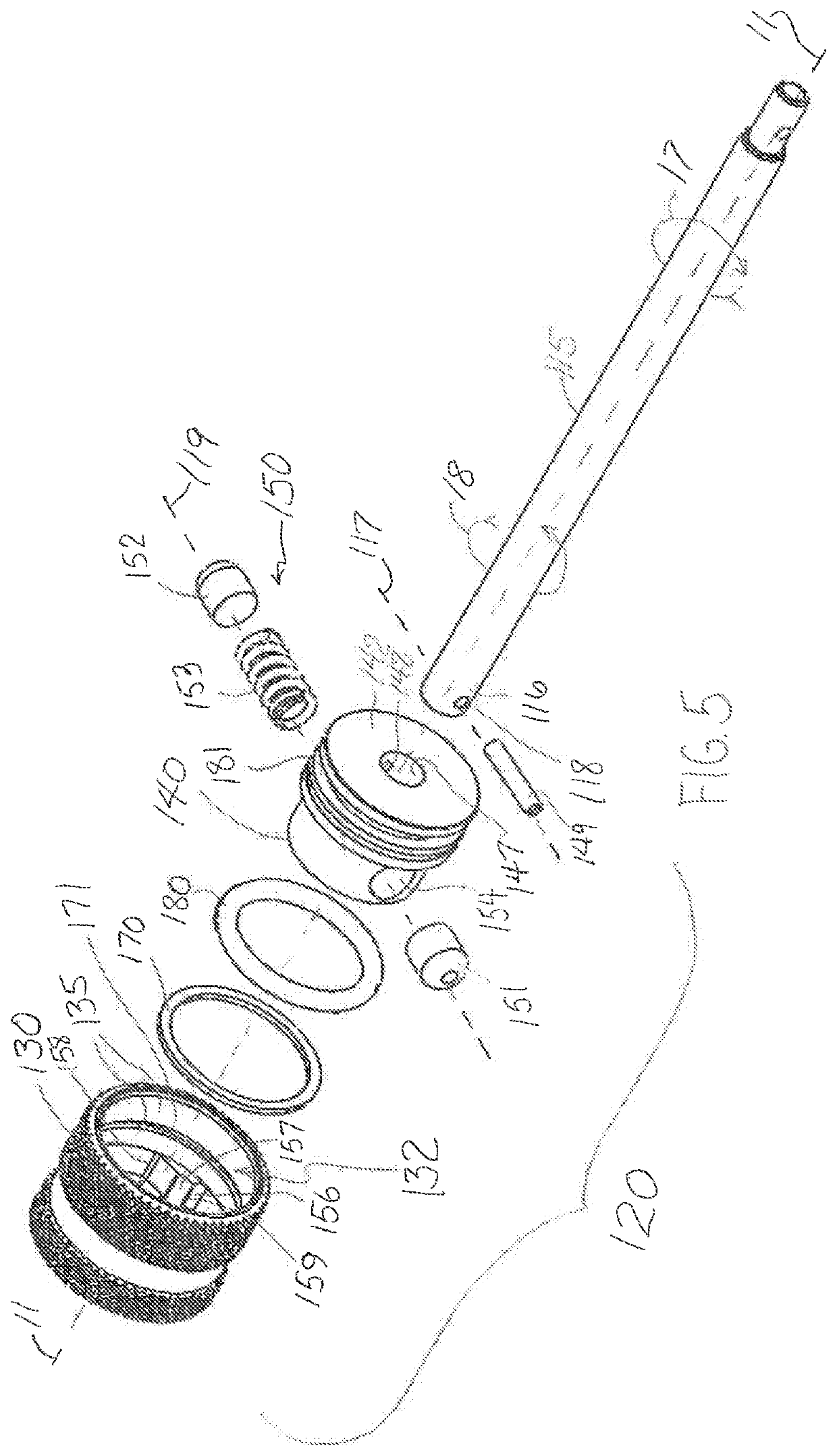
An apparatus includes a tool holder, a knob, and a clutch coupling the tool holder to the knob and including a biasing element disposed between a first detent button and a second detent button. The knob defines an internal surface with an engaging surface disposed facing the tool holder and defining a first wedge-shaped protuberance that includes a first stop surface and a first ramp surface. The distal ramp surface is disposed contacting one of the first detent button and the second detent button when the knob rotates in the first rotational direction about the central longitudinal axis. The distal stop surface is disposed to contact one of the first detent button and the second detent button when the knob plate rotates in the second rotational direction about the central longitudinal axis.

Description

CROSS-REFERENCE TO RELATED APPLICATIONS[0001]This application claims priority to US provisional patent application serial no. 62-808,473 filed on Feb. 21, 12019, which is hereby incorporated herein by this reference for all purposes. This application claims priority to US provisional patent application serial no. 62-959,554 filed on Jan. 10, 2020, which is hereby incorporated herein by this reference for all purposes.STATEMENT REGARDING FEDERALLY SPONSORED RESEARCH OR DEVELOPMENT[0002]Not applicable.FIELD OF THE INVENTION[0003]The subject matter disclosed herein generally involves apparatus for removing and installing a valve core from a sealed system that is not at atmospheric pressure.BACKGROUND OF THE INVENTION[0004]HVAC units that are charged with environmentally harmful refrigerants are maintained at pressures that differ from the atmospheric pressure that surrounds the HVAC unit. These HVAC units are fitted with valves that include valve cores that periodically must be replace...

Claims


Application Information

Patent Timeline
IPC IPC(8): B25B23/142F16K51/00B25B27/24
CPCB25B23/1427B25B27/24F16K51/00B25B13/48B25B13/481B25B23/141F16K31/46
Inventor JONES, ERIC SCOTT
Owner ANDERSON BRASS
Features
  • R&D
  • Intellectual Property
  • Life Sciences
  • Materials
  • Tech Scout
  • Unparalleled Data Quality
  • Higher Quality Content
  • 60% Fewer Hallucinations
Learn More