Holding structure for cable

a technology of holding structure and cable, which is applied in the direction of cables, insulated conductors, conductors, etc., can solve the problems of affecting the sealing effect of portions, affecting the sealing effect, and taking time, and achieve the effect of reliable sealing

Active Publication Date: 2020-08-27
AUTONETWORKS TECH LTD +2
View PDF0 Cites 5 Cited by
  • Summary
  • Abstract
  • Description
  • Claims
  • Application Information

AI Technical Summary

Benefits of technology

[0019]According to the above-described configuration, the sheath is held by the first clamping portion and the second clamping portion, and the cap is held by an engagement groove and an engagement protrusion. Accordingly, the relative positions of the sheath and the cap can be reliably held. Accordingly, the rubber plug is reliably pressed against the sheath an

Problems solved by technology

However, the above-described configuration was problematic in that it took time for performing the process of filling the tubular member with the sealing material.
This is because if the sheath and the pl

Method used


Image

  • Holding structure for cable
  • Holding structure for cable
  • Holding structure for cable

Examples


embodiment 1

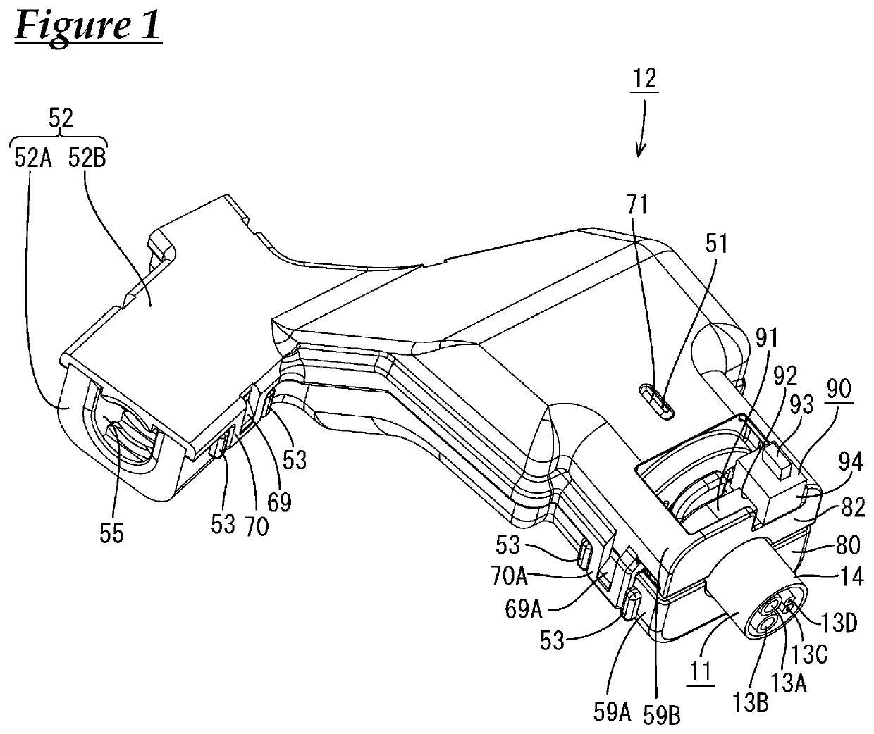
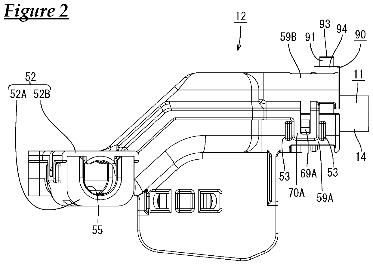
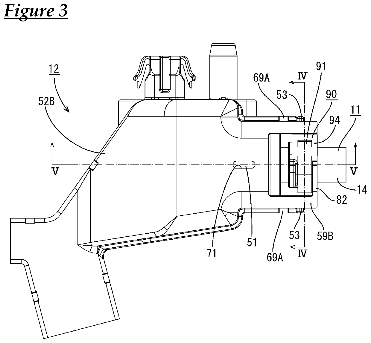
[0032]Embodiment 1 to which the technology disclosed in this specification is applied to a holding structure 12 for a cable 11 will be described with reference to FIGS. 1 to 11. The present embodiment can be applied to a wire harness for an electrical parking brake that is installed in a vehicle (not shown), for example. As shown in FIG. 1, the holding structure 12 includes the cable 11 and a holder 52 configured to hold the cable 11. In the following description, “top” refers to the upper side in FIG. 2, and “bottom” refers to the lower side in FIG. 2. Note that the above-described directions are used for convenience of the description, and the holding structure 12 can be disposed in any orientation with respect to the vehicle.

[0033]The rubber plug 15 is fitted around an end portion 14A of the sheath 14 of the cable 11. The cap 17 is fitted around this rubber plug 15. The cable 11 and the cap 17 are held by the holder 52.

[0034]As shown in FIG. 1, the cable 11 according to the prese...


PUM


Abstract

A holding structure for a cable includes a cable in which electrical wires extend out from an end portion of a sheath, a first holder provided with a first clamping portion, a second holder provided with a second clamping portion configured to clamp the cable between the first clamping portion and the second clamping portion, a rubber plug that has a plurality of through-holes through which the electrical wires respectively are passed, and that is held by the first holder and the second holder, in a state in which the rubber plug is fitted around the end portion of the sheath, and a binding member that is wrapped around the first clamping portion and the second clamping portion.

Description

CROSS REFERENCE TO RELATED APPLICATIONS[0001]This application claims the priority of Japanese patent application JP2015-249633 filed on Dec. 22, 2015, the entire contents of which are incorporated herein.TECHNICAL FIELD[0002]The present invention relates to a holding structure for a cable.BACKGROUND ART[0003]Conventionally, a waterproof structure as disclosed in JP 2003-17476A (Patent Document 1) is known as a structure for waterproofing terminal portions of a multicore cable. In this structure, a tubular member is fitted around a front end of a sheath of the multicore cable from which a plurality of electrical wires are drawn out, and this tubular member is filled with a sealing material such as a silicone-based adhesive.[0004]In the above-described multicore cable, first, the front end of a nozzle is inserted into a gap between the sheath and the tubular member, and a sealing material is injected from the front end of the nozzle, the front end of the nozzle is then inserted betwee...

Claims


Application Information

Patent Timeline
IPC IPC(8): B60R16/02H02G3/32H01B7/00H02G15/013
CPCH02G15/013B60R16/0215H01R2201/26H01B7/0045H02G3/32
Inventor KOMORI, HIROKAZUSADAHIRO, YOSHINORIHATTORI, HIDEKI
Owner AUTONETWORKS TECH LTD
Why Eureka
Try Eureka