
Depression operated tilting pump apparatus and cab tilting system employing the pump apparatus

a technology of tilting pump and cab, which is applied in the direction of loading-carrying vehicle superstructure, vehicle components, superstructure subunits, etc., can solve the problems of difficulty in tilting cab weight, difficulty in operating tilting pump, and inconvenience in using tools for operating tilting pump, so as to reduce the hassle of pre-work, reduce the difficulty of operation, and improve the merchantability of the vehicle cab tilting system

Active Publication Date: 2020-08-27
HYUNDAI MOTOR CO LTD +1
View PDF0 Cites 0 Cited by
  • Summary
  • Abstract
  • Description
  • Claims
  • Application Information

AI Technical Summary

Benefits of technology

The present patent aims to provide a solution for the difficulties and inconveniences in operating a tilting pump for vehicles. The patent describes a depression operated tilting pump apparatus that is easy to store and handle by integrating a stay rod and the tilting pump with each other using a mudguard. The fixed stay rod and the movable stay rod are adjusted with respect to each other to allow the movable stay rod to be rotated by depression force of the mudguard and to be transmitted by rotational force of the tilting pump. The apparatus is designed to eliminate hassle, difficulty, and inconveniences in operating the tilting pump and to increase merchantability of the vehicle cab tilting system. The technical effect of the present disclosure is to provide a more efficient and convenient way to tilting vehicles cab.

Problems solved by technology

First, hassle of pre-work for operating the tilting pump, which is caused because the tilting bar is received inside the front panel of a vehicle so that in order to tilt the cab, and thus, it is necessary to locate and pull out the tilting bar after opening the door and then opening the front panel by releasing locking of the front panel.
Second, difficulty in operating the tilting pump; this is caused because it is required to manually reciprocate the tilting bar connected to the tilting pump upward and downward in order to operate the tilting pump.
Third, inconvenience in using tools for operating the tilting pump; this is caused because it is not only impossible to operate the tilting pump when the tilting bar is lost but also difficulty in tilting the cab is weighted because of excessive working effort due to short length of the tilting bar.

Method used


Image

  • Depression operated tilting pump apparatus and cab tilting system employing the pump apparatus
  • Depression operated tilting pump apparatus and cab tilting system employing the pump apparatus
  • Depression operated tilting pump apparatus and cab tilting system employing the pump apparatus

Examples


Embodiment Construction

[0041]Exemplary embodiments of the present disclosure will be described below in detail with reference to the accompanying drawings. Since these embodiments described herein by way of example may be implemented in many different forms by those of ordinary skill in the field of art to which the present disclosure pertains, the present disclosure is not limited thereto.

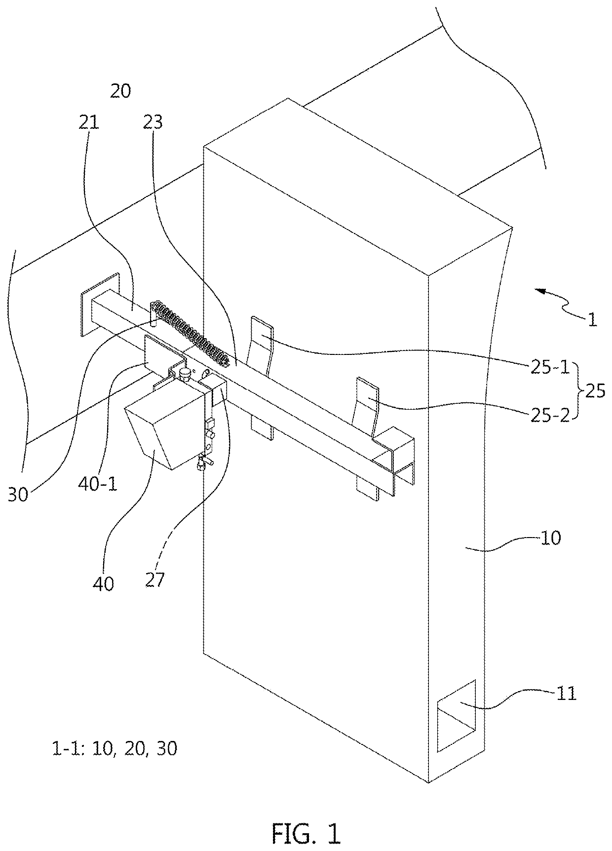
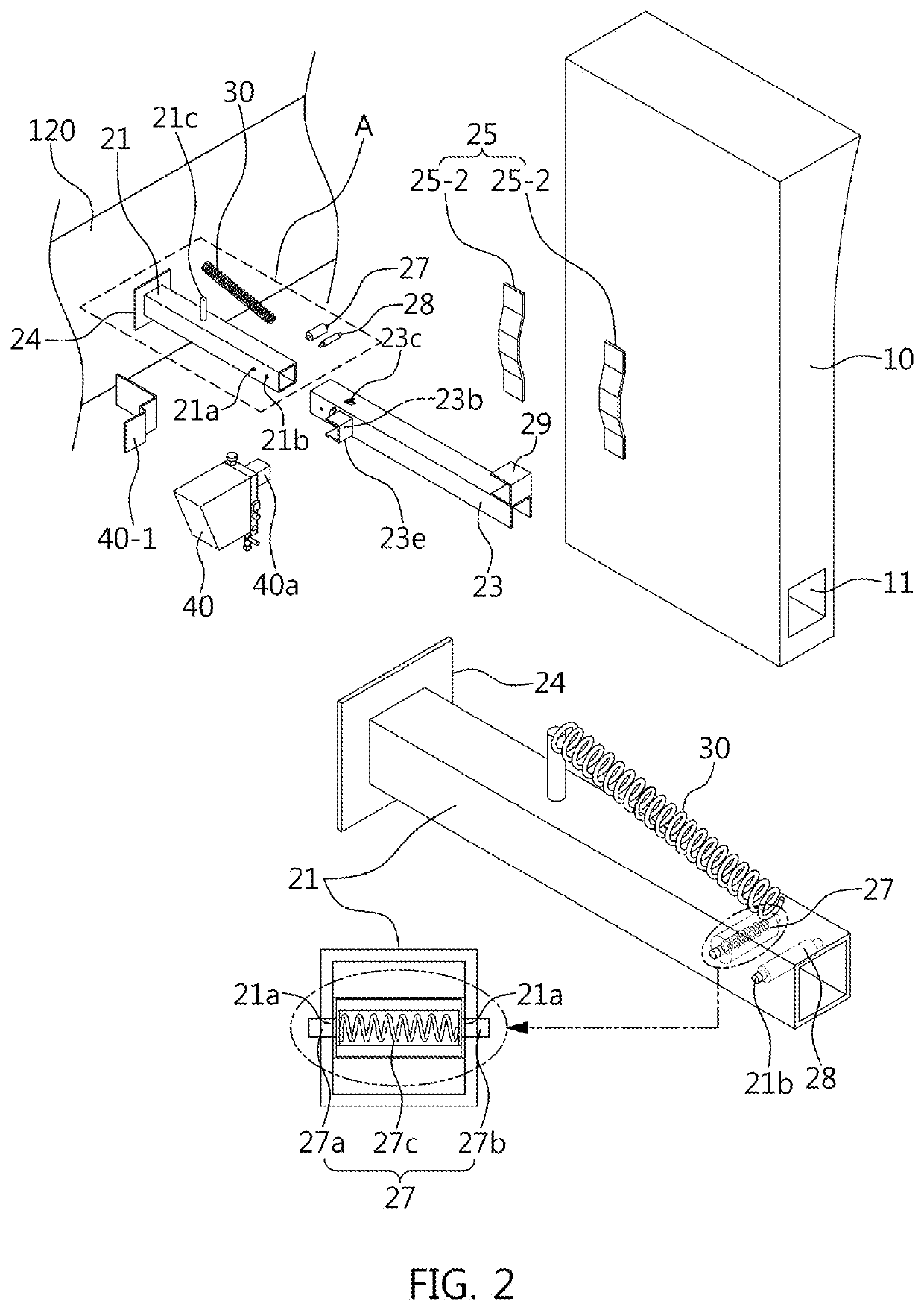
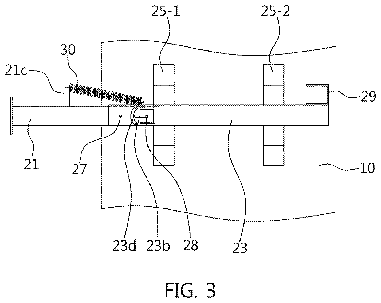
[0042]Referring to FIG. 1, a tilting pump apparatus 1 comprises a pump operation unit 1-1 and a tilting pump 40 for generating hydraulic pressure. Particularly, the tilting pump apparatus 1 is characterized as a depression operated tilting pump apparatus because the pump operation unit 1-1 is configured such that upward and downward reciprocating motion of a mudguard 10 is converted into rotational force of the tilting pump 40 by means of stay rods 21 and 23.

[0043]Specifically, the pump operation unit 1-1 is composed of the mudguard 10, a stay member 20 and a restoring spring 30.

[0044]For example, the mudguard 10 is mad...


PUM


Abstract

A tilting pump apparatus includes a pump operation unit arranged between a mudguard, which is configured to obstruct foreign objects entering from a front side, and a tilting pump, which is configured to be rotated for generating hydraulic pressure to transmit movement of the mudguard generated by depressing the mudguard as rotational force for rotating the tilting pump.

Description

CROSS-REFERENCE TO RELATED APPLICATION[0001]This application claims priority to Korean Patent Application No. 10-2019-0021944, filed on Feb. 25, 2019 in the Korean Intellectual Property Office, the disclosure of which is incorporated herein by reference in its entirety.TECHNICAL FIELD[0002]The present disclosure relates to a cab tilting apparatus, and more particularly, to a cab tilting system employing a tilting pump apparatus that is operated by foot depressing operation using a mudguard.BACKGROUND[0003]In general, a cabin (simply referred to as “cab”) can be tilted by means of a cab tilting system whereby an engine room can be opened to the outside.[0004]To this end, the cab tilting system comprises a tilting pump apparatus wherein the tilting pump apparatus is composed of: a tilting pump for supplying hydraulic pressure (or pneumatic pressure) that is connected, by a hydraulic line, to a cab tilting stay (or a tilting cylinder) for pushing the cab upward in a state where the cab...

Claims


Application Information

Patent Timeline
Patent Type & Authority Applications(United States)
IPC IPC(8): B62D33/067B62D25/18F15B15/14
CPCF15B15/1457B62D33/067B62D25/182F15B15/1447F15B15/16B62D33/07B62D25/16B60Y2400/406
Inventor KIM, YOUNG-SHIN
Owner HYUNDAI MOTOR CO LTD
Learn More