Multirotor joined-wing aircraft with vtol capabilities

a technology of joining wings and aircraft, applied in the direction of propellers, vertical landing/take-off aircraft, transportation and packaging, etc., can solve the problems of reduced structural weight efficiency, increased load levels on respective aircraft structures, and lack of safe boarding zones, so as to reduce structural weight efficiency, reduce structural efficiency, and increase load levels

Active Publication Date: 2020-08-27
AIRBUS URBAN MOBILITY GMBH
View PDF0 Cites 14 Cited by
  • Summary
  • Abstract
  • Description
  • Claims
  • Application Information

AI Technical Summary

Benefits of technology

[0013]In any case, a major drawback of conventional VTOL multirotor aircrafts consists in a lack of safe boarding zones which allow for a safe and free access, for boarding or for emergency exiting, to a respective passenger cabin of a given VTOL multirotor aircraft without exposition to adjacently arranged thrust producing units that essentially produce lift. Furthermore, in conventional VTOL multirotor aircrafts there are generally discrepancies between spread lift, as a result of a low-interactive multirotor arrangement, and centralized mass, which causes larger load levels on a respective aircraft structure and consequently reductions of the structural weight efficiency. Moreover, large overhead masses are usually created when arranging lifting surfaces such as wings and / or thrust producing units that essentially produce lift ahead of the fuselage, which results in a need of strong frames within the fuselage to cope with safety requirements in emergency landing or crash conditions, hence resulting in additional largely loaded structures and to an associated decrease of structural efficiency. In addition, lift or forward thrust producing units are often arranged in such a way that their respective rotor discs are impacting the aircraft's cabin, which leads to serious safety risks in blade loss scenarios, hence further requiring protection means for the passengers and further penalties in weight efficiency. Finally, many conventional VTOL multirotor aircrafts use undesirable battery locations close to the passengers within the central fuselage, i. e. behind, below or aside the cabin, which represents a serious safety penalty in case of sudden inflammation of the batteries during flight or after crash. It is, therefore, an object of the present invention to provide a new multirotor aircraft that is adapted for vertical take-off and landing and that enables safe operation, in particular by providing freely and securely accessible boarding zones to passengers. The new multirotor aircraft should preferably be provided with a braced-wing configuration that overcomes the above-described drawbacks and that exhibits an improved architectural arrangement of respective wings in combination with an improved thrust producing units distribution to achieve an improved structural weight efficiency whilst ensuring improved safety characteristics for boarding and emergency landings.

Problems solved by technology

In any case, a major drawback of conventional VTOL multirotor aircrafts consists in a lack of safe boarding zones which allow for a safe and free access, for boarding or for emergency exiting, to a respective passenger cabin of a given VTOL multirotor aircraft without exposition to adjacently arranged thrust producing units that essentially produce lift.
Furthermore, in conventional VTOL multirotor aircrafts there are generally discrepancies between spread lift, as a result of a low-interactive multirotor arrangement, and centralized mass, which causes larger load levels on a respective aircraft structure and consequently reductions of the structural weight efficiency.
Moreover, large overhead masses are usually created when arranging lifting surfaces such as wings and / or thrust producing units that essentially produce lift ahead of the fuselage, which results in a need of strong frames within the fuselage to cope with safety requirements in emergency landing or crash conditions, hence resulting in additional largely loaded structures and to an associated decrease of structural efficiency.
In addition, lift or forward thrust producing units are often arranged in such a way that their respective rotor discs are impacting the aircraft's cabin, which leads to serious safety risks in blade loss scenarios, hence further requiring protection means for the passengers and further penalties in weight efficiency.
Finally, many conventional VTOL multirotor aircrafts use undesirable battery locations close to the passengers within the central fuselage, i. e. behind, below or aside the cabin, which represents a serious safety penalty in case of sudden inflammation of the batteries during flight or after crash.

Method used


Image

  • Multirotor joined-wing aircraft with vtol capabilities
  • Multirotor joined-wing aircraft with vtol capabilities
  • Multirotor joined-wing aircraft with vtol capabilities

Examples


Embodiment Construction

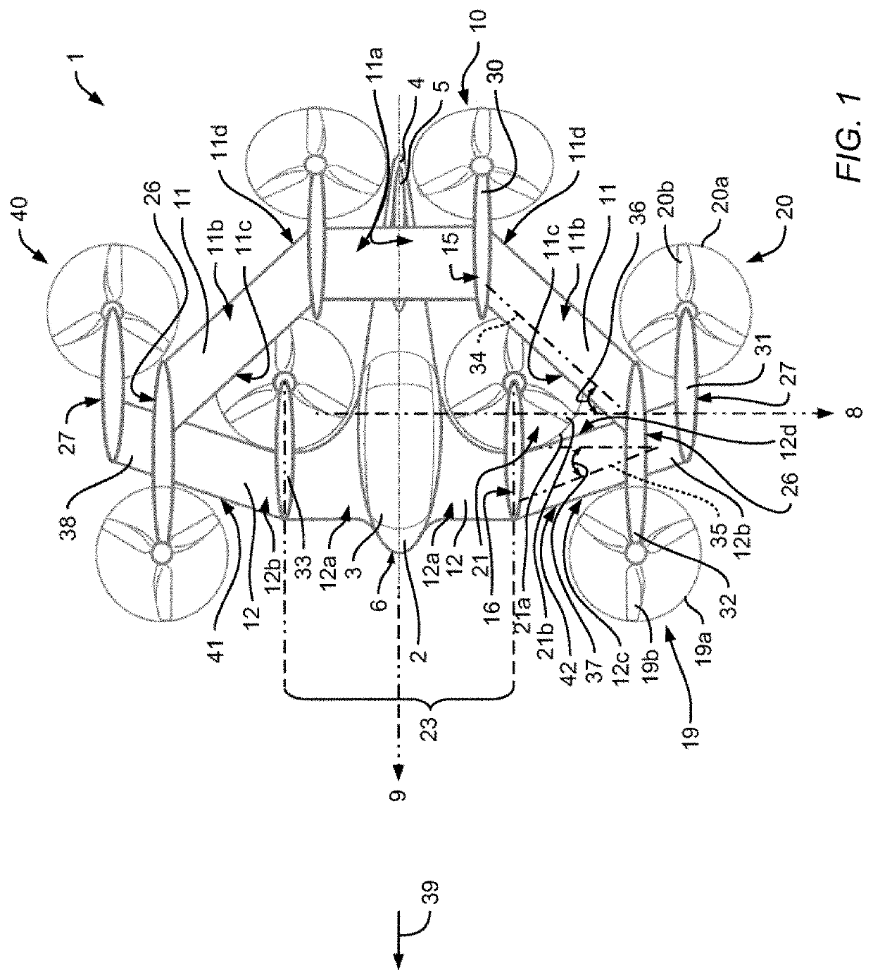
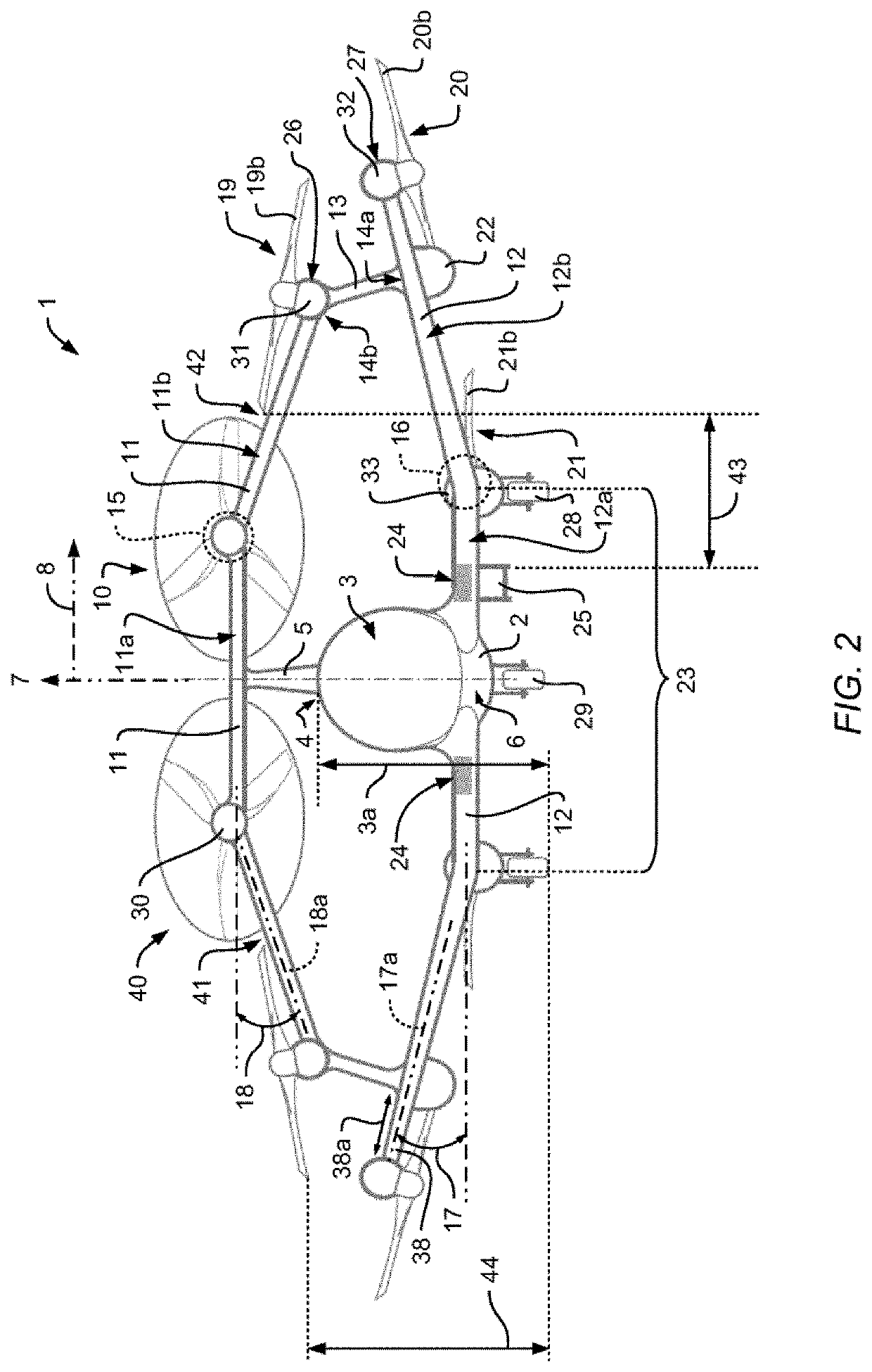
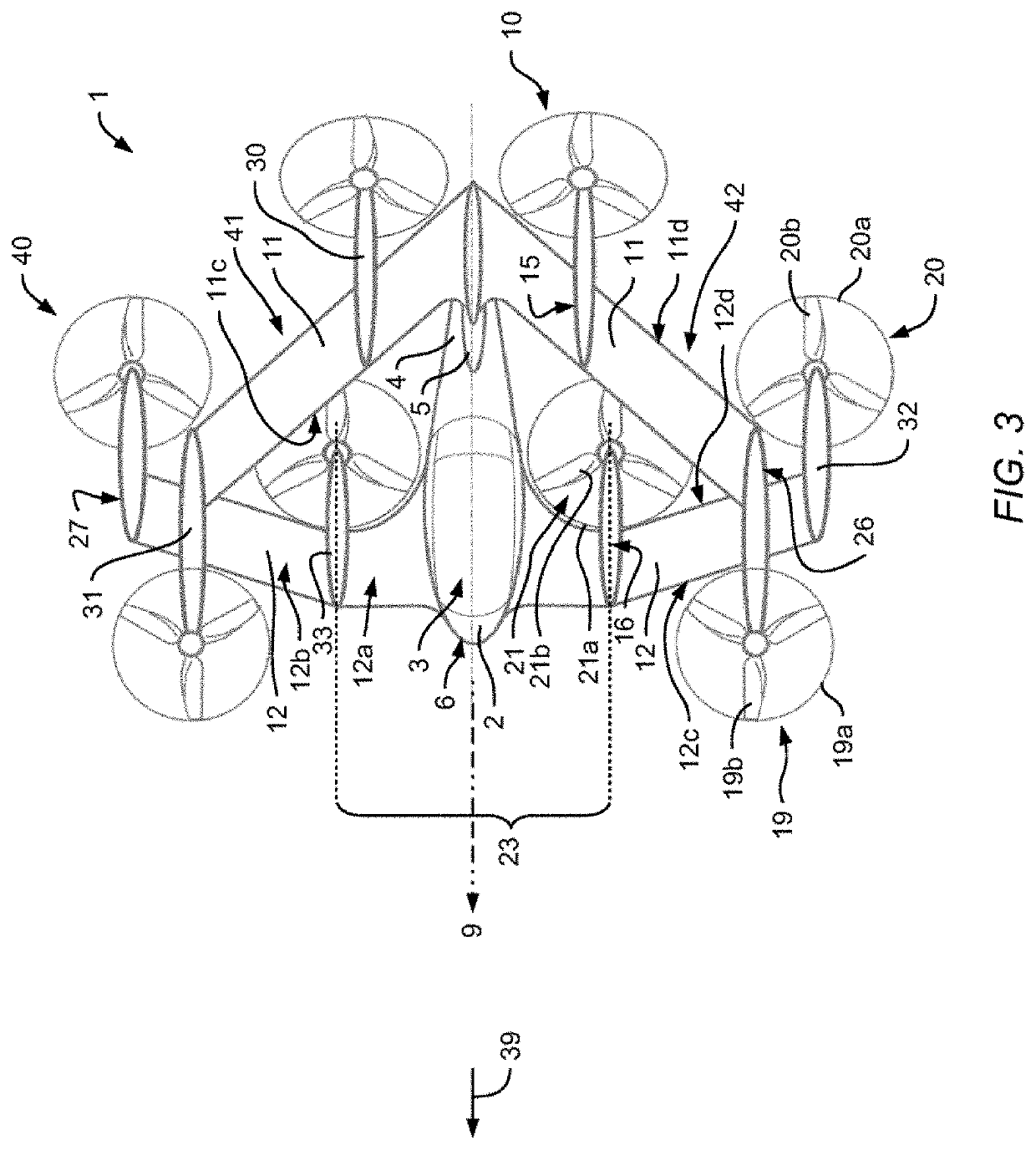
[0058]FIG. 1 shows a multirotor aircraft 1 that is adapted for vertical take-off and landing and that is referred to as the “VTOL multirotor aircraft 1” hereinafter, for simplicity and clarity. A forward flight direction of the VTOL multirotor aircraft 1 is exemplarily shown by an arrow 39.

[0059]For purposes of illustration, the VTOL multirotor aircraft 1 is shown with three mutually orthogonal directions forming a three-dimensional frame of reference. A “longitudinal” direction corresponds to a respective roll axis 9 that is inherent to the VTOL multirotor aircraft 1, which is also referred to as “X-axis 9” hereinafter. Another direction, said to be “transverse”, is perpendicular to the roll axis 9 and corresponds to a respective pitch axis 8 of the VTOL multirotor aircraft 1. This transverse direction is also referred to as “Y-axis 8” hereinafter. A respective XY-plane formed by the X- and Y-axes 9, 8 is considered to be “horizontal” and corresponds to a top view plane of the VTOL...


PUM


Abstract

A multirotor aircraft that is adapted for vertical take-off and landing. The multirotor aircraft comprises a fuselage, a tail boom that is provided with a vertical fin, a thrust producing units assembly that is provided for producing thrust in operation, at least one lower wing which comprises a lower wing inboard section that is connected to the fuselage and a lower wing outboard section that forms a lower wing tip, and at least one upper wing which is connected to the vertical fin and which forms an upper wing tip. The at least one upper wing is joined to the at least one lower wing in a joined-wing configuration.

Description

CROSS-REFERENCE TO RELATED APPLICATIONS[0001]This application claims priority to French patent application No. EP 19400005.5 filed on Feb. 27, 2019, the disclosure of which is incorporated in its entirety by reference herein.BACKGROUND OF THE INVENTION(1) Field of the Invention[0002]The invention is related to a multirotor aircraft that is adapted for vertical take-off and landing, comprising a fuselage, a tail boom, a thrust producing units assembly that is provided for producing thrust in operation, at least one lower wing, and at least one upper wing, wherein the at least one upper wing is joined to the at least one lower wing in a joined-wing configuration.(2) Description of Related Art[0003]Various conventional multirotor aircrafts that are adapted for vertical take-off and landing (VTOL) and which are hereinafter referred to as “VTOL multirotor aircrafts” are known, e. g. from the documents EP 2 551 190 A1, EP 2 551 193 A1, BP 2 551 198 A1, EP 2 234 883 A1, EP 2 571 762 A1, EP...

Claims


Application Information

Patent Timeline
Patent Type & Authority Applications(United States)
IPC IPC(8): B64C39/06B64C39/04B64C5/06B64C29/00B64C3/16B64C1/24B64C11/00
CPCB64C11/007B64C39/04B64C29/0025B64C3/16B64C39/068B64C5/06B64C1/24B64C27/08B64C27/12B64C27/22B64D27/24B64D27/26B64C27/26
Inventor FINK, AXELKIESEWETTER, UWEKICKER, KLAUS
Owner AIRBUS URBAN MOBILITY GMBH
Why Eureka
Try Eureka