Cantilevered tension-leg stabilization of buoyant wave energy converter or floating wind turbine base

a technology of tension legs and wind turbines, which is applied in the direction of mechanical equipment, mechanical energy handling, machines/engines, etc., can solve the problems of limited effectiveness of multiple tension legs attached directly to floating or semi-submerged bases, restricted self-orientation (weather-vanning) of the base and any attached wec device, and submerged depth of such bases, etc., to achieve the effect of low capex, limited effectiveness against lateral motion stabilization, and light weigh

Active Publication Date: 2020-08-27
ROHRER TECH
View PDF0 Cites 3 Cited by
  • Summary
  • Abstract
  • Description
  • Claims
  • Application Information

AI Technical Summary

Benefits of technology

[0019]In one aspect of the disclosure, it is desirable to have a floating base or platform such as a WEC base, FWT base, or combination WEC-FWT base motion-stabilized or controlled against wave or wind-induced motions. It is further desirable to have such bases be as light-weight and inexpensive (low CapEx) as possible. Multiple tensioned leg or cable connections between the base and the seabed can provide supplemental seabed stabilization mass for such a base but will restrict desirable self-orientation (weather-vanning) of the base and any attached WEC device. WEC self-orientation is desirable because it allows wide-beam WEC surface floats to intercept maximum wave-front-containing wave energy per unit of float volume, mass, and cost (CapEx). Multipl

Problems solved by technology

Multiple tensioned leg or cable connections between the base and the seabed can provide supplemental seabed stabilization mass for such a base but will restrict desirable self-orientation (weather-vanning) of the base and any attached WEC device.
Multiple tension legs attached directly to such floating or semi-submerged bases are also of limited effectiveness against lateral

Method used


Image

  • Cantilevered tension-leg stabilization of buoyant wave energy converter or floating wind turbine base
  • Cantilevered tension-leg stabilization of buoyant wave energy converter or floating wind turbine base
  • Cantilevered tension-leg stabilization of buoyant wave energy converter or floating wind turbine base

Examples


Embodiment Construction

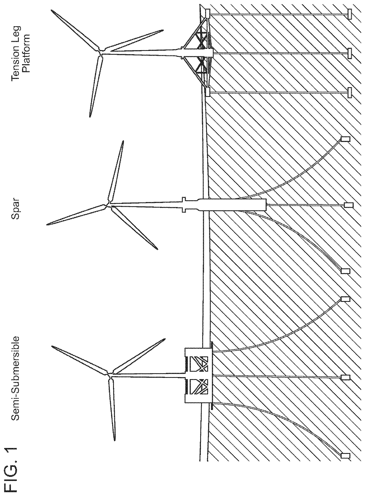
[0039]Referring now to FIG. 1, three of the most generic proposed FWT bases are illustrated, the Semi-Submersible, the Spar (Buoy or Mono-Spar), and the Tension Leg Platform, respectively from left to right. The Spar-Buoy is employed by Equinor in their Hywind Scotland project using five 6 MW FWTs. It utilizes a buoyant semi-submerged elongated vertical spar, with a typical submerged depth of ⅓rd to ⅔rds the length of the above SWL wind turbine tower. The submerged spar section is typically of hollow construction with at least the lower portion having one or more cavities for the admission (and expulsion) of seawater ballast. High density solid ballast (typically metal or concrete) is usually placed at or near the bottom to maximize the distance between the center of buoyancy and the center of gravity (including the mass of the wind turbine and its tower) for improved pitch stability. The Spar-Buoy semi-submerged base is slack moored via multiple cables.

[0040]The Semi-Submersible is...


PUM


Abstract

A device to stabilize, reduce, or control the wave or wind-induced heave (vertical), surge (lateral), or pitching (rolling) motion of a floating or semi-submerged buoyant base, raft, barge, buoy or other buoyant body such as the buoyant base of a wave energy converter or a floating wind turbine base. The device concurrently allows the floating base to self-orient or weathervane to substantially maintains its orientation with respect to the direction of oncoming waves, winds, or wind gusts. The device also facilitates maintaining the submerged depth or vertical orientation of the buoyant base relative to the still water line to compensate for tidal depth changes. The device utilizes a second substantially submerged buoyant body having a center of buoyancy and at least one tensioned seabed connection located substantially below and forward or up-sea or up-wind of the center of buoyancy of the buoyant base. A structural member, which can optionally also be buoyant or integral with the base or second submerged body, connects the submerged buoyant body with the floating base.

Description

CROSS-REFERENCE TO RELATED APPLICATIONS[0001]This application is a Continuation-In-Part of U.S. Regular Utility application Ser. No. 16 / 153,688, filed Oct. 5, 2018, which is a continuation of U.S. Regular Utility application Ser. No. 15 / 286,539, filed Oct. 5, 2016, now U.S. Pat. No. 10,094,356, issued Oct. 9, 2018, which is a Continuation-In-Part of U.S. Regular Utility application Ser. No. 14 / 530,723, filed Nov. 1, 2014, now U.S. Pat. No. 9,863,395, issued Jan. 9, 22018, which is a Continuation-In-Part of U.S. Regular Utility application Ser. No. 14 / 101,325, filed Dec. 9, 2013, now U.S. Pat. No. 9,127,640, issued Sep. 8, 2015, which is a Continuation-In-Part of U.S. Regular Utility application Ser. No. 13 / 506,680, filed May 8, 2012, now U.S. Pat. No. 8,614,520, issued Dec. 24, 2013, the contents all of which are incorporated in their entirety herein by reference.FIELD OF THE DISCLOSURE[0002]This disclosure relates to an improved means to stabilize a floating or semi-submerged appar...

Claims


Application Information

Patent Timeline
IPC IPC(8): F03B13/18H02K7/18
CPCY02E10/30F03B13/186H02K7/18F05B2270/18F03B13/182F03B13/1815F03B13/181F05B2240/93F05B2220/705Y02E10/72Y02E60/16
Inventor ROHRER, JOHN W.
Owner ROHRER TECH
Why Eureka
Try Eureka