Sleeve and shield terminal manufacturing method

Inactive Publication Date: 2020-08-27
SUMITOMO WIRING SYST LTD
View PDF0 Cites 4 Cited by
  • Summary
  • Abstract
  • Description
  • Claims
  • Application Information

AI Technical Summary

Benefits of technology

This invention is related to a barrel for pressing an insulating portion of a sleeve used in electrical power transmission. The invention includes a sleeve with a convex portion that bulges out over its entire circumference. This enhances the flexural rigidity of the sleeve, making it harder to crush during the pressing of the barrel. The convex portion is crushed and elongated by the barrel, preventing excessive compression of the insulating portion. An end convex portion and concave portion are also formed, further increasing the flexural rigidity and preventing insulating portion compression. Additionally, the barrel may be designed to contact the shield, further increasing the flexural rigidity and preventing insulating portion compression. These technical features enhance the performance of the insulating portion and improve the overall quality of the barrel.

Problems solved by technology

Thus, a tip of each projection may strongly bite into the insulating portion and the insulating portion may be partially crushed or cut when the barrel is crimped.
In contrast, sufficient flexural rigidity may not be ensured with a general-purpose sleeve having a hollow cylindrical shape and a constant diameter over the entire length.
When the barrel is crimped, the sleeve itself may be crushed to compress the insulating portion excessively.

Method used


Image

  • Sleeve and shield terminal manufacturing method
  • Sleeve and shield terminal manufacturing method
  • Sleeve and shield terminal manufacturing method

Examples


Embodiment Construction

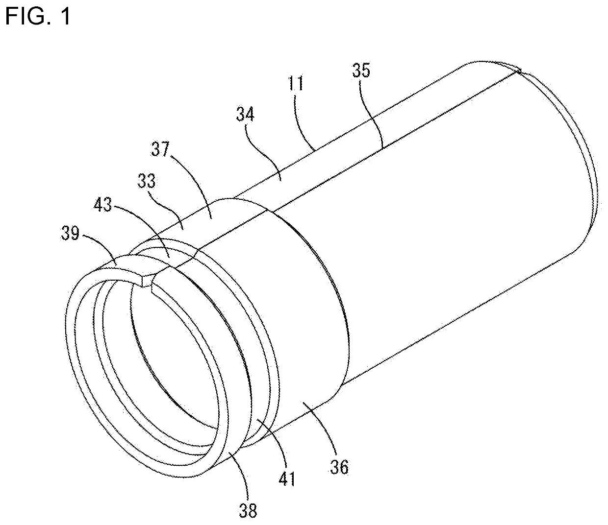
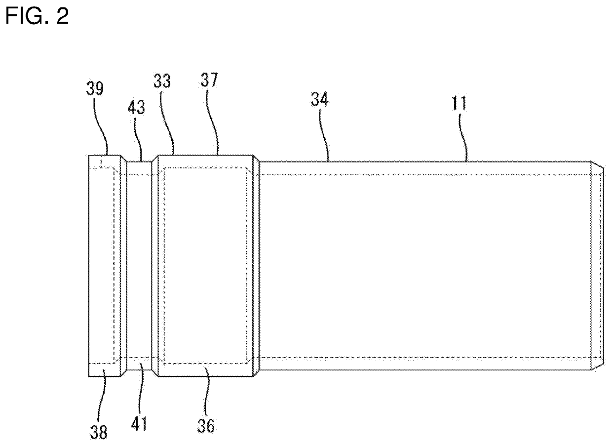
[0021]One embodiment of the invention is described with reference to FIGS. 1 to 6. A sleeve 11 of this embodiment is provided in a shield terminal 10 having a shielding function, and is connected to an end part of a shielded cable 60.

[0022]60>

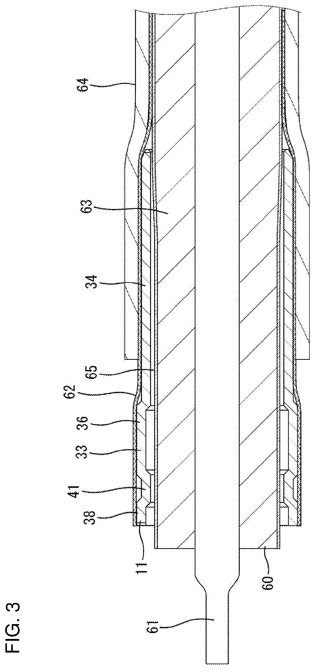
[0023]The shielded cable 60 is a coaxial cable and, as shown in FIGS. 3 and 4, includes a core 61 made of a conductor for transmitting a high-frequency signal, and a shield 62 made of a braided wire surrounds the core 61. An insulating portion 63 made of insulating resin covers the outer periphery of the core 61, and the shield 62 covers the outer periphery of the insulating portion 63. A sheath 64 made of insulating resin covers the outer periphery of the shield 62. In this embodiment, a layer of a metal foil 65, such as a copper foil, is provided between the insulating portion 63 and the shield 62. The layer of the metal foil 65 functions to adjust an impedance in a transmission path to a specified value.

[0024]The sheath 64 is removed in a pr...


PUM


Abstract

A sleeve (11) is a hollow cylindrical member provided in a shield terminal (10), and pressable by a wire barrel (18) by being arranged between an insulating portion (63) and a shield portion (62) of a shielded cable (60). A convex portion (36) shaped to bulge radially outward over an entire circumference is provided at an intermediate position of the sleeve (11) in an axial direction. The convex portion (36) is crushed and elongated by the wire barrel (18) of an outer conductor terminal (13). The insulating portion (63) can be prevented from being excessively compressed.

Description

BACKGROUNDField of the Invention[0001]The invention relates to a sleeve and a shield terminal manufacturing method.Related Art[0002]A shield terminal having a shielding function is connected to an end part of a coaxial cable (shielded cable). Japanese Unexamined Patent Publication No. 2010-232046 discloses a sleeve provided in a shield terminal. The sleeve is inserted between a braided wire and an insulating portion inside the braided wire on an end part of the shield terminal.[0003]The sleeve has a hollow cylindrical shape and is provided with projections at three positions spaced apart in a circumferential direction. The projections support the insulating portion at three points in the circumferential direction.[0004]A barrel is crimped to the sleeve together with the braided wire. Japanese Unexamined Patent Publication No. 2010-232046 describes that an air layer is formed between the insulating portion and the sleeve by the respective projections to compensated for an impedance r...

Claims


Application Information

Patent Timeline
IPC IPC(8): H01R9/05H01R43/048
CPCH01R9/0518H01R43/048H01R24/40H01R24/44H01R13/6581H01R43/04H01R2103/00H01R4/20H01R4/185
Inventor HASHIMOTO, NORIHITOKANEMURA, KEISUKEKUBOTA, MOTOKIKANG, LIPINGMITSUI, SHOHEIYAMANAKA, WATARUKASUGA, MASANOBUHIRANO, AIYAMADA, RYO
Owner SUMITOMO WIRING SYST LTD
Why Eureka
Try Eureka